background image

13

9

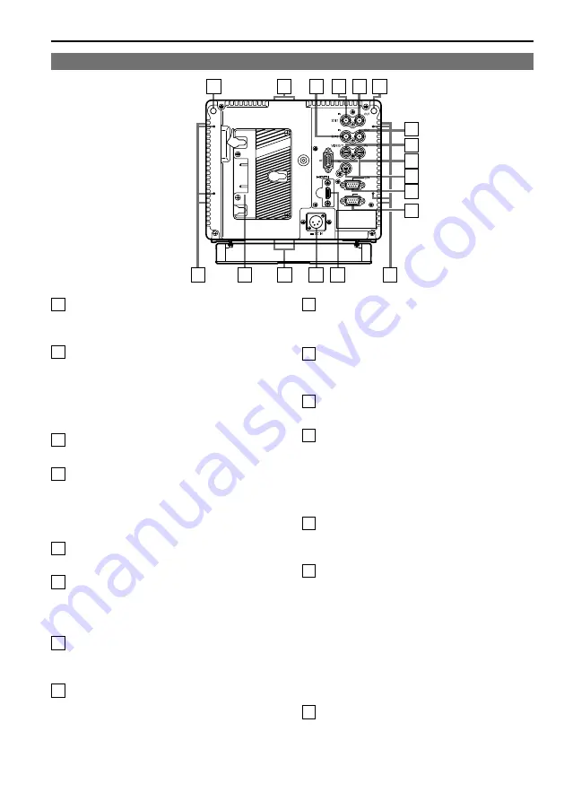
  REAR TALLYS (red)

Can be lit by a control signal from a GPI/
camera.

10

  SDI1 (HD/SD) input terminal (BNC)

This is the SDI1 input terminal. (Compatible 
with HD/SD automatic switching, Compatible 
with 3G-SDI)
When you use 3D assist mode (page 51), input 
images for the left eye (L).

11

  SDI1 active through output terminal

This terminal outputs SDI1 input as is.

12

  SDI2 (HD/SD) input terminal (BNC)

This is the SDI2 input terminal. (Compatible 
with HD/SD automatic switching)
When you use 3D assist mode (page 51), input 
images for the right eye (R).

13

  SDI2 active through output terminal

This terminal outputs SDI2 input as is.

14

  VIDEO/Y input terminal (BNC)

This is the VIDEO signal (component signal) 
input terminal/Y signal (analog component 
signal) input terminal.

15

  P

B

/P

R

 input terminal (BNC)

This is the P

B

/P

R

 signal (analog component 

signal) input terminal.

16

  VF terminal (D-SUB, 15 pins)

This terminal connects to the VF (viewfinder) 
terminal of broadcasting and business cameras 
made by Panasonic.
The unit can be used as the viewfinder for such 
a camera.

17

  GPI input terminal (D-SUB, 9 pins)

External control is possible by using a GPI 
signal.

18

  SERIAL terminal (D-SUB, 9 pins)

External control is possible by using an RS-
232C interface.

19

  HDMI input terminal

This is the HDMI input terminal.

20

  DC IN terminal (XLR, 4 pins)

This is the external DC power supply input 
terminal.
When a DC power supply is connected 
concurrently with the battery, the external 
power input takes precedence.

21

  Battery holder

This holder is used with a battery made by 
Anton/Bauer. (page 14)

22

  Screw holes for fixing tripod

There are two screw holes on both the top and 
bottom for fixing the unit to a tripod (compatible 
with 3/8-16UNC). A removable adapter is 
installed in one of the screw holes on the top 
of the unit, and enables a 1/4-20UNC screw 
to fit in the screw hole. Decide whether to 
use the adapter depending on the diameter 
of the tripod’s fixing screw. Use a flat-blade 
screwdriver to remove or install the adapter.

23

  Screw holes for multi-purpose fixing

There are four screw holes (M3) for multi-
purpose fixing on the rear of the unit, and two 
on each the left and right.

Controls and Their Functions

 (continued)

Rear panel

11

12 10

9

22

19

21

20

23

23

13

14

15

16

17
18

22

9

SERIAL

Summary of Contents for BT-LH910G

Page 1: ...1HM0 PS D Printed in Japan ENGLISH Model No BT LH910G Operating Instructions LCD Video Monitor Before operating this product please read the instructions carefully and save this manual for future use VQT3N15 ...

Page 2: ...Notice U S A only Disposal may be regulated in your community due to Environmental considerations For disposal or recycling information please visit Panasonic website http www panasonic com environmental or call 1 888 769 0149 FCC NOTICE USA This device complies with part 15 of the FCC Rules Operation is subject to the following two conditions 1 This device may not cause harmful interference and 2...

Page 3: ...ations for analog audio signals Other connecting cables IEEE1394 USB Use shielded cables which provide quality performance for high frequency applications as connecting cables When connecting to the DVI signal terminal use a cable with a ferrite core If your apparatus is supplied with ferrite core s they must be attached on cable s following instructions in this manual 3 Performance level The perf...

Page 4: ...cles and the point where they exit from the apparatus 11 Only use attachments accessories specified by the manufacturer 12 Use only with the cart stand tripod bracket or table specified by the manufacturer or sold with the apparatus When a cart is used use caution when moving the cart apparatus combination to avoid injury from tip over 13 Unplug this apparatus during lightning storms or when unuse...

Page 5: ... VF CONFIG 37 FUNCTION 38 GPI 47 INPUT SELECT 48 AUDIO 49 DISPLAY SETUP 50 CONTROL 51 HOURS METER 51 3D Assist Mode 52 MIRROR Left Right and Top Bottom inversion 54 SHIFT Horizontal and Vertical Shift 54 COMPARISON Composition Check 54 CONVERGENCE Convergence Check 55 COLOR Color Check 55 ZOOM FOCUS Zoom and Focus Check 56 VERTICAL Vertical Offset Check 57 OVERLAY Parallax Check 58 Setting Item Re...

Page 6: ...of water on the case turn off the power and wait until the condensation has evaporated Some video images may appear blurred on the screen Leaving the unit in a location exposed to high temperature and humidity for an extended period of time may damage the LCD screen and cause blurring Do not use the unit in excessively dusty environments Doing so may damage the LCD screen Using the unit in cases s...

Page 7: ...on time required for 3D shooting Wide Variety of Functions and Interfaces Equipped with 3G SDI SDI HD SD compatible HDMI VIDEO and YP BPR inputs FOCUS IN RED function Displayed abbreviated to F IN R in the picture adjusting knob status display Making camera focus adjustments is extremely easy because the section of the image in focus is displayed in red to make it easy to understand what is in foc...

Page 8: ... dB How to Select Area of Use Connect the unit to the power supply turn on the power and press the MENU button 111 The MAIN MENU screen appears Press 222 to select SYSTEM CONFIG and press ENTER The SYSTEM CONFIG submenu screen appears Press 333 to select AREA SETTING and press ENTER The AREA SETTING value turns green Press 444 to select the area of use from NTSC NTSC J PAL and press ENTER The YES ...

Page 9: ...1 48 5 1 15 16 148 5 5 7 8 230 9 1 16 195 7 7 11 16 118 2 4 5 8 46 1 13 16 170 6 11 16 98 5 3 7 8 183 7 3 16 214 5 8 7 16 20 2 13 16 204 8 1 16 3 8 16UNC 1 3 8 16UNC 46 1 13 16 17 55 11 16 3 8 1 6 U N C 3 8 1 6 U N C 20 2 13 16 210 8 1 4 When the adapter is connected 1 4 20UNC 1 ...

Page 10: ... VF INT SG VIDEO Video input SDI1 Serial digital interface input compatible with 3G HD SD SDI2 Serial digital interface input compatible with HD SD HDMI HDMI input YPBPR Analog component input VF Viewfinder input VF YPBPR VF VIDEO 1 INT SG Internal chart for adjustment Color Bar Grayscale page 74 The input line when the power supply is switched ON is the one that was selected the last time the pow...

Page 11: ... menu item assigned to FUNCTION3 When the control lock is on the key mark appears and FUNCTION does not operate In 3D assist mode the item of FUNCTION3 is forcefully fixed to the 2D image adjustment mode item 2D ADJUST 5 Picture and volume adjusting knobs lamps Functions in 2D image adjustment mode Knob1 PEAK PEAKING 0 30 0 PHASE 0 60 30 R GAIN R BIAS page 32 Knob2 CHROMA 0 60 30 F IN R page 46 0 ...

Page 12: ... is on the key mark appears and setting values cannot be changed page 51 When the MONO function is ON page 31 PHASE and CHROMA operations are disabled F IN R is enabled during operation of the FOCUS IN RED function While operating HV DELAY page 41 when set to any other setting than OFF BRIGHT operation is disabled The CONTRAST and BACK LIGHT operations are disabled in BLACK MODE For the operating ...

Page 13: ...uch a camera 17 GPI input terminal D SUB 9 pins External control is possible by using a GPI signal 18 SERIAL terminal D SUB 9 pins External control is possible by using an RS 232C interface 19 HDMI input terminal This is the HDMI input terminal 20 DC IN terminal XLR 4 pins This is the external DC power supply input terminal When a DC power supply is connected concurrently with the battery the exte...

Page 14: ...eries for which connection verified ENDURA E 7S ENDURA E HL9 ENDURA E 10 Install the V mount type adapter plate 111 Insert the battery pack and slide it in the 222 direction of the arrow Reference To remove the adapter plate Slide it in the opposite direction to the one in which it was attached while keeping the release lever on the adapter plate pulled down all the way Notes For details on the V ...

Page 15: ...res a current that exceeds the output rating of a Panasonic camera recorder DC IN socket 1 GND 4 12 V 4 3 2 1 Notes Use a shield cable with a length of 2 m 6 56 feet or less for the DC cord Use of cords any longer than 2 m 6 56 feet may result in noise appearing on the screen If the battery pack and an external DC power supply are connected simultaneously then the external DC power supply will hav...

Page 16: ...pack attached the camera platform may be damaged Use an external DC power supply Contact your vendor for details of broadcasting and business camera recorders that will be launched in the future Panasonic camera recorders that allow the unit to be connected as a VF viewfinder Panasonic Camera recorder VF Video Signals 1 VF Communication Monitor Camera Camera Monitor 2 YPBPR VIDEO ZEBRA 3 TALLY Ind...

Page 17: ...t When attaching the tilt stand make sure to align the protrusions for alignment with the corresponding alignment holes Alignment hole Notes When tilting the monitor be careful not to trap a hand between the monitor and stand When not using the tilt stand take care that the unit does not fall over When the unit will be permanently installed in one place we recommend securing it in place using the ...

Page 18: ...gs of the camera used in combination with the unit For details see the instruction manual of the camera 6 Various displays lock setting This indicates that the front operations lock is on page 51 7 DC power supply voltage display DC power supply voltage is displayed 8 Battery level display When you are using an Anton Bauer battery with a battery level display function the battery level is indicate...

Page 19: ... name page 11 Picture and volume adjusting knobs White An item not target for adjustment Green An item target for adjustment Gray An item which cannot be adjusted Sharpness display SHARPNESS H 30 Indicates the SHARPNESS H V setting value of the VIDEO CONFIG menu If no operation is performed for 2 minutes the setting value is confirmed and the display disappears Function display F1 WFM VECTOR F2 PI...

Page 20: ...ellow Reference point not included to 0 dB point Red Overrange Time code TC display NDF DF Use the menu to display the time code for HD SDI signal input It also allows you to switch display mode VITC LTC VUB LUB page 50 In VITC and LTC display mode Displays the time code in hours minutes seconds or frames In drop frame mode a different delimiter between seconds and frames is used Note Read errors ...

Page 21: ...area depending on the specified window position and size In such a case the window will be displayed but if the window also extends out of the entire screen the display position of the window will be changed so that the window is displayed inside the entire screen DC power supply voltage and battery level display DC14 0V 50 DC power supply voltage is displayed The battery level display is displaye...

Page 22: ...22 to select a menu and press ENTER MENU EXIT SEL ENTER ENTER MAIN MENU 2D 3D ASSIST MARKER VIDEO CONFIG SYSTEM CONFIG VF CONFIG FUNCTION GPI INPUT SELECT DISPLAY SETUP CONTROL HOURS METER 2D Press 333 to select a sub menu and press ENTER The settings in the sub menu change to green MENU EXIT SEL ENTER ENTER MARKER MARKER 16 9 4 3 BACK CENTER GPI MARKER1 GPI MARKER2 MARKER TYPE CROSS HATCH SIZE OF...

Page 23: ...LAST EBU OFF NTSC Changes to green Press 444 to select a USER1 to USER5 file to save the settings to and press ENTER The following screen appears MENU EXIT SEL ENTER ENTER SETUP SAVE USER1 YES NO Select YES and press ENTER 555 This saves the user data To return to the previous screen press 666 MENU Loading user data Press MENU to display the MAIN menu 111 Press 222 to select the SYSTEM CONFIG menu...

Page 24: ... AREA SETTING GPI CONTROL GPI1 GPI2 GPI3 GPI4 GPI5 GPI6 GPI7 GPI8 VIDEO FORMAT NTSC SETUP SDI1 SDI2 HDMI YPBPR COMPONENT LEVEL VF VIDEO YPBPR SIGNAL TYPE INT SG AUDIO SELECT L SELECT R LEVEL METER CH SELECT POINT LINE CH INFO HEAD ROOM MARKER 16 9 4 3 BACK CENTER GPI MARKER1 GPI MARKER2 MARKER TYPE CROSS HATCH SIZE FUNCTION1 FUNCTION2 FUNCTION3 FUNCTION DISPLAY USER0 63 D93 D65 D56 VAR1 VAR2 VAR3 ...

Page 25: ...e displayed image is 16 9 OFF No marker display 4 3 4 3 marker 13 9 13 9 marker 14 9 14 9 marker CNSCO 2 39 2 39 1 marker CNSCO 2 35 2 35 1 marker 2 1 2 1 marker VISTA VISTA marker 95 95 area marker 90 90 area marker 80 80 area marker 93 93 1 area marker TYPE1 93 area marker TYPE2 88 89 5 area marker TYPE1 88 area marker TYPE2 USER Area marker that is adjustable in 1 increments within a range of 8...

Page 26: ... the aspect ratio of the vertical 93 1 and 88 the aspect ratio of the vertical 89 The factory preset setting value is 85 BACK 2 NORMAL HALF BLACK Selects the background brightness around the marker NORMAL Normal background HALF 50 background brightness BLACK 0 background brightness black CENTER 2 OFF ON Displays the center marker OFF Turns the display off ON Turns the display on Main Menu continue...

Page 27: ... 88 4 3 88 area marker for 4 3 aspect ratio 80 4 3 80 area marker for 4 3 aspect ratio USER 4 3 User settings area marker for 4 3 aspect ratio GPI MARKER2 5 MARKER TYPE 6 TYPE1 TYPE2 Selects conventional monitor or camera recorder marker size TYPE1 Conventional monitor marker size TYPE2 Marker size compliant with the camera recorder Panasonic made CROSS HATCH HIGH LOW OFF Turns the cross hatch gri...

Page 28: ... marker 2 35 2 39 The marker is displayed as a vertical dotted line when UNDER is selected under SCAN in the VIDEO CONFIG menu VISTA marker 2 1 marker CNSCO marker 2 35 2 39 Area marker A dotted line is displayed as the marker 95 Area marker 93 Area marker 90 Area marker 88 Area marker 80 Area marker USER Area marker 1 You can adjust the value within the range of 80 to 100 in increments of 1 by pr...

Page 29: ...r 80 Area marker USER Area marker 1 You can adjust the value within the range of 80 to 100 in increments of 1 by pressing 1 You can display the 4 3 marker and the 16 9 marker simultaneously Simultaneous display example The section becomes the MARKER BACK It controls the background of the marker selected with a 16 9 ratio 4 3 marker 16 9 marker 16 9 marker 95 area marker 4 3 marker 80 area marker C...

Page 30: ... Level Video Gamma VARICAM OTHER COLOR TEMP USER 0 63 2 D93 D65 D56 VAR1 VAR2 VAR3 Selects color temperature USER 0 63 Adjustable settings 0 63 equivalent to a color temperature range of 3 000 K 9 300 K D93 Equivalent to a color temperature of 9 300 K D65 Equivalent to a color temperature of 6 500 K D56 Equivalent to a color temperature of 5 600 K VAR1 WB adjustment mode 3 VAR2 WB adjustment mode ...

Page 31: ...SD signal input 4 3 4 3 display 16 9 16 9 display SCAN 6 NORMAL UNDER Sets under scan and normal display NORMAL Normal display UNDER Under scan The following sharpness values are available and the settings for the selected input signal is displayed 4 Adjustment status during selection appears at the bottom left of the screen 1 VIDEO system input VIDEO the factory defaults are SHARPNESS MODE LOW an...

Page 32: ...lues These are the adjustments made before shipment from the factory Adjusts the GAIN elements for RED For numerical value confirmation GREEN Adjusts the GAIN elements for GREEN For numerical value confirmation BLUE Adjusts the GAIN elements for BLUE For numerical value confirmation BIAS Adjusts the BIAS elements Press ENTER to switch to RGB direct adjustment mode This allows you to begin adjustin...

Page 33: ...9 511 456 CONT B LIGHT VOLUME BRIGHT PEAK PHASE CHROMA F IN R You can switch between GAIN and BIAS by pressing the corresponding knob If you press ENTER in the GAIN menu GAIN adjustment is displayed first If you press ENTER in the BIAS menu BIAS adjustment is displayed first When you access the mode from a FUNCTION button GAIN adjustment is displayed first The adjustment item name and the numerica...

Page 34: ...ternal DC power supply Near end is approximately 11 3 V TYPE2 Select this when you will mainly use a battery Near end is approximately 13 3 V SETUP LOAD 3 USER5 4 USER4 4 USER3 4 USER2 4 USER1 4 FACTORY Loads saved factory defaults FACTORY or user data USER1 USER5 page 23 After loading user data the screen displays the signal selected before user data was loaded SETUP SAVE USER5 USER4 USER3 USER2 ...

Page 35: ...N function in this unit measures LCD panel characteristics from low to high brightness values and internal monitor processing handles CALIBRATION CALIBRATION does not rely on image quality settings since internal signals are used for a calibration CALIBRATION in this unit is made at D65 color temperature and other color temperatures are results calculated automatically from this value Equipment re...

Page 36: ...and use this submenu to make a calibration Select AUTO CALIBRATION and select YES in the confirmation screen that appears to start calibration RESET 2 Returns calibration data to their factory defaults Select RESET and select YES in the confirmation screen that appears to return calibrated values to their factory defaults EXECUTING is displayed during AUTO CALIBRATION and COMPLETE appears when cal...

Page 37: ...he underlined values are factory preset setting values Sub menu Settings Description VF CONTROL VF CH ALL CH Used to select the input line for the VF function of the monitor VF function tally lamps red and green lit zebra displayed displayed aspect changed SD VF CH Only enabled when the VF line is selected ALL CH Enabled with all input lines REAR TALLY OFF ON Used to allow control of the tally lam...

Page 38: ...the following order GAMMA STANDARD GAMMA FILM GAMMA STDIO PST GAMMA STANDARD SD ASPECT 2 3 Switches between 16 9 and 4 3 SCAN 2 3 Switches between UNDER SCAN and NORMAL SCAN SUB WINDOW 1 Sets the split screen function The display changes in the following order SINGLE FULL PART STILL SINGLE WFM VECTOR 2 Displays waveform or vector display For details on the available operation items refer to page 4...

Page 39: ...ed FUNCTION DISPLAY 8 OFF ON1 ON2 9 Selects display of functions assigned to FUNCTION1 FUNCTION3 front panel buttons It also selects button action 1 touch 2 touch off OFF No function display ON1 1 touch action to display and perform functions ON2 2 touch action to display and perform functions If a FUNCTION button is pushed during the picture adjusting knobs display the picture adjusting knobs dis...

Page 40: ...t SUB WINDOW PIXEL TO PIXEL 3D ASSIST When HDMI 640 x 480 input MARKER When GPI is set SUB WINDOW 3D ASSIST When HDMI 640 x 480 input WHITE BALANCE When other than VAR1 to VAR3 selected in COLOR TEMP PIXEL TO PIXEL Enabled when 1080i p signal input When other than 1080i p signal input SUB WINDOW 3D ASSIST FOCUS IN RED When WFM is ON When GPI is set When INT SG is selected LEVEL METER When other th...

Page 41: ...e of 4 3 is displayed in the second half section PIXEL TO PIXEL PIXEL TO PIXEL OFF PIXEL TO PIXEL CENTER PIXEL TO PIXEL LT PIXEL TO PIXEL RT PIXEL TO PIXEL RB PIXEL TO PIXEL LB PIXEL POSITION PIXEL TO PIXEL OFF PIXEL TO PIXEL CENTER PIXEL TO PIXEL LT PIXEL TO PIXEL RT PIXEL TO PIXEL RB PIXEL TO PIXEL LB FOCUS IN RED FOCUS IN RED OFF FOCUS IN RED ON ZEBRA ZEBRA OFF ZEBRA ON REAR TALLY REAR TALLY OF...

Page 42: ...e Video PART Resizes the main window to show only its center to also display a second image two sub windows Normal window main window Before memory two sub windows After memory two sub windows Video Press the button again Video Video Press the button again Still image Video Crops the image to show its center part The cropped main window image is placed side by side with a second image These exampl...

Page 43: ...ECTOR function has been assigned to any of the FUNCTION1 to FUNCTION3 buttons WFM is displayed in the order of the Y signal R signal G signal and B signal Normal screen WFM display Y R G B VECTOR display 1 Press the button again Press the button again WFM waveform display VECTOR vector display These examples show 16 9 aspect ratio images Displayed only for SDI signal input 1 The scale display is a...

Page 44: ...g values Item Settings Description PIXEL TO PIXEL 1 2 OFF ON Sets whether to display the screen display size at the input signal size OFF Not displayed ON Displayed Compatible formats 1080 60i 59i 50i 60p 59p 50p 30p 29p 25p 24p 23p 25PsF 24PsF 23PsF PIXEL POSITION CENTER LT RT RB LB Positions the display of signals in PIXEL TO PIXEL mode CENTER Center of the screen LT Left Top RT Right Top RB Rig...

Page 45: ...page 27 Each press of the button FUNCTION1 to FUNCTION3 page 38 to which the CROSS HATCH has been assigned turns the function on and off This assumes that the CROSS HATCH function has been assigned to any of the FUNCTION1 to FUNCTION3 buttons Each press of the FUNCTION button to which the CROSS HATCH function is assigned changes the display as shown Press the button again back to original image wi...

Page 46: ...tion is displayed the detection sensitivity level 0 30 can be changed with the F IN R knob A higher numerical value results in lower detection sensitivity outlines are displayed in red even when they are not in focus properly If you set CHROMA to 0 or assign MONO to another function button to switch to monochrome the focus will become easier to check These examples show 16 9 aspect ratio images Pu...

Page 47: ...OFF MARKER2 ON OFF MARKER BACK HALF MARKER BACK BLACK CENTER MARKER INPUT SEL VIDEO INPUT SEL SDI1 INPUT SEL SDI2 INPUT SEL HDMI INPUT SEL YPBPR INPUT SEL VF INPUT SEL INT SG SD ASPECT SCAN R TALLY G TALLY MONO GAMMA SEL FILM GAMMA SEL STDIO PST PIXEL TO PIXEL FOCUS IN RED REMOTE STANDBY Assigns functions to the GPI control terminal pins The same items can be set to each terminal page 62 Note Oper...

Page 48: ...nent signal input level SMPTE Signal level complies with SMPTE and PB and PR are 0 7 V p p at 100 chroma B75 Select this when connecting a Betacam or similar device with a setup function Adjusts the interior of the monitor to the 7 5 setup level to suit the black level B00 Select this when connecting a Betacam or similar device without a setup function VF OFF ON Sets or cancels VF line for the INP...

Page 49: ...s the channel displayed on the meter on and off HEAD ROOM 5 12dB 18dB 20dB Sets the display position of the reference point in the meter display If the input signal is SD when CH5 to CH8 is selected 1 The channel can be switched from CH5 CH1 CH6 CH2 CH7 CH3 and CH8 CH4 The menu settings remain as is When an HDMI signal is input the audio of CH1 is output to the headphones L regardless of the menu ...

Page 50: ...cale TIME CODE OFF ON Turns the time code display on and off MODE SELECT LTC VITC LUB VUB Selects time code display mode LTC Displays linear time code LTC VITC Displays vertical interval time code VITC LUB Displays user bits included in LTC VUB Displays user bits included in VITC CLOSED CAPTION OFF ON Turns closed caption display on and off 2 CC TYPE CEA 608 CEA 708 Selects the closed caption disp...

Page 51: ...ABLE menu items are available when the lock is engaged The picture adjusting knob is disabled when the lock is engaged The FUNCTION buttons cannot be operated when the lock is engaged The LOCAL ENABLE setting determines operations in lock mode The key mark is displayed during lock engagement MAIN MENU 2D 3D ASSIST MARKER VIDEO CONFIG SYSTEM CONFIG VF CONFIG FUNCTION GPI INPUT SELECT DISPLAY SETUP ...

Page 52: ... L R images on a checkerboard pattern to enable the brightness or color offset to be checked ZOOM FOCUS Side by side Enlarges part of an image to enable the focus offset or zoom offset to be checked VERTICAL Side by side Displays the horizontal line markers to enable the vertical offset to be checked OVERLAY Overlay Displays the vertical line markers to enable the width of parallax to be checked H...

Page 53: ...sist mode dedicated functions are assigned to the picture adjusting knobs and FUNCTION3 button in the control section on the front panel When you want to make picture adjustments switch to 2D mode To make picture adjustments while still in 3D assist mode press the FUNCTION3 button to turn ON the 2D picture quality adjustment mode and then switch the function of the adjusting knob to the 3D assist ...

Page 54: ...lay the images You can check the lens axis of a rig type camera system while checking the rotation offset of the image H V FUNC 0 0 SHFT Screen L R are overlaid in one screen Note The setting information for shifting images with the SHIFT function is not memorized The initial display state is restored when you switch to the COMPARISON function or another assist function Sub menu Operation Settings...

Page 55: ...hing AUTO Automatic switching MANUAL Knob2 turn L R Selects the image to display when the MODE menu is MANU L Image of L side R Image of R side SPEED Knob3 turn SLOW FAST Selects the speed for when the MODE menu is auto switching SLOW Every 1 second FAST Every 4 frames When 720P Every 8 frames COLOR Color Check This function overlays and displays the SDI1 L image and SDI2 R image on a checkerboard...

Page 56: ...s set to ON When 1080 signal input OFF C LT CT RT RB CB LB OFF Displays two screens side by side C Center of screen LT Top left of screen CT Top center of screen RT Top right of screen RB Bottom right of screen CB Bottom center of screen LB Bottom left of screen When 720P signal input OFF C L R OFF Displays two screens side by side C Center of screen L Left of screen R Right of screen F IN R Knob2...

Page 57: ...nts trying your hardest to eliminate camera vertical offset The underlined values are factory preset setting values Sub menu Operation Settings Description EXPAND Knob1 press DISP 1 2 Selects the display screen DISP Displays the full screen 1 x1 Displays the screen with the actual number of pixels PIXEL TO PIXEL 2 x2 Expands the actual number of pixels to x2 in the vertical direction only and then...

Page 58: ...mphasized gray display Assist Point If the parallax is way too large stereoscopic vision will become difficult when 3D images are viewed so check the width of parallax of the L side and R side images using the width of the vertical line markers as a reference The underlined values are factory preset setting values Sub menu Operation Settings Description OVERLAY Knob1 turn STD GRAY Selects overlay ...

Page 59: ...IG GAMMA SELECT FILM GAMMA COLOR TEMP SHARPNESS MODE SHARPNESS H SHARPNESS V I P MODE MONO ANAMO 1 2 3 3 3 3 3 3 3 3 3 SD ASPECT 1 2 3 3 3 3 SCAN 1 2 SYSTEM CONFIG SUB WINDOW MENU POSITION STATUS DISPLAY BATTERY REMAIN WARNING VOLTAGE SETUP LOAD SETUP SAVE POWER ON SETUP COLOR SPACE POWER SAVE MODE CALIBRATION AREA SETTING VF CONFIG VF CONTROL REAR TALLY ZEBRA FUNCTION FUNCTION1 FUNCTION2 FUNCTION...

Page 60: ...TOR 1 2 4 4 4 4 4 4 4 4 POSITION 1 2 VECTOR MODE 1 2 3 3 3 3 3 3 3 3 VECTOR SCALE 1 2 3 3 3 3 3 3 3 3 TIME CODE 3 3 3 3 3 3 3 3 3 3 MODE SELECT 3 3 3 3 3 3 3 3 3 3 CLOSED CAPTION 3 3 3 3 3 3 3 3 CC TYPE 3 3 3 3 3 3 3 3 3 CAPTION CHANNEL 3 3 3 3 3 3 3 3 CAPTION SERVICE 3 3 3 3 3 3 3 3 3 3 CONTROL CONTROL LOCAL ENABLE HOURS METER OPERATION LCD IMAGE ADJUSTMENT PEAKING PHASE CHROMA BRIGHT CONTRAST BA...

Page 61: ...NG VF CONFIG VF CONTROL REAR TALLY ZEBRA FUNCTION FUNCTION1 2 FUNCTION2 2 FUNCTION3 FUNCTION DISPLAY Settings Input CH SDI1 SDI2 HD GPI GPI CONTROL GPI1 GPI8 INPUT SELECT VIDEO FORMAT NTSC SETUP SDI1 SDI2 HDMI YPBPR COMPONENT LEVEL VF VIDEO YPBPR SIGNAL TYPE INT SG AUDIO SELECT L SELECT R LEVEL METER CH SELECT POINT LINE CH INFO HEAD ROOM DISPLAY SETUP WFM VECTOR 3 4 POSITION 3 4 VECTOR MODE 3 4 V...

Page 62: ...GPI8 Assigned item Function Operating conditions UNDEF Undefined no function assigned MARKER1 ON OFF 1 Switches marker display defined in GPI MARKER1 page 27 in the MARKER menu Level operation Short circuited ON Open OFF MARKER2 ON OFF 1 Switches marker display defined in GPI MARKER2 page 27 in the MARKER menu Level operation Short circuited ON Open OFF MARKER BACK HALF 2 Reduces the brightness of...

Page 63: ...taneously go on the tally color changes to orange 3 When remote standby is set to ON the CONT and B LIGHT LEDs on the front flash 4 If the GPI terminal to be assigned is set to a short circuited state first and then MENU is operated to set 5 this item the backlight turns off and the screen display disappears so MENU operation becomes unable to be checked To change the setting of this item be sure ...

Page 64: ...ng with STX and ending with ETX Append any data after the colon following the command as required Response formats Setting command response 111 STX 02h Command ETX 03h Query command response 222 STX 02h Data ETX 03h Error response 333 STX 02h Error codes ETX 03h Error codes ER001 Invalid command ER002 Parameter error SERIAL terminal External operations can be performed via the RS 232C interface Th...

Page 65: ...0 CONTINUE 1 3SEC OFF 2 OFF DSD 9 DMK Marker settings 16 9 marker MK100 OFF MK101 80 MK102 88 MK103 93 MK104 95 MK105 14 9 MK106 13 9 MK107 4 3 MK108 90 MK109 CNSCO 2 35 MK110 VISTA MK111 2 1 MK112 CNSCO 2 39 MK1 080 MK1 100 range of 80 100 4 3 marker MK200 OFF MK201 80 MK202 88 MK203 93 MK204 95 MK208 90 MK2 080 MK2 100 range of 80 100 Marker background BAK0 NORMAL BAK1 HALF BAK2 BLACK Center mar...

Page 66: ...T SG 2 QPC Image quality adjustment CON Contrast setting value 00 60 BRI Brightness setting value 00 60 CRO Chroma setting value 00 60 PHA Phase setting value 00 60 VOL Volume setting value 00 60 3 QBO Blue only 0 OFF 1 ON 4 QBL Backlight 000 100 5 QCH Cross hatch 0 OFF 1 LOW 2 HIGH 6 QCW Cross hatch Size 0 40 1 80 7 QMK marker MAK Area marker 1 00 OFF 01 80 02 88 03 93 04 95 05 14 9 06 13 9 07 4 ...

Page 67: ...ODE2 13 QMO Monochrome 1 OFF 2 ON 14 QAS SD Aspect 0 16 9 1 4 3 15 QSC Scan 0 NORMAL 1 UNDER 16 QFR Format 01 1080 60i 02 1080 59 94i 03 1080 50i 1080 25PsF 04 1080 30p 05 1080 29 97p 06 1080 25p 07 1080 24p 08 1080 23 98p 09 1080 24PsF 10 1080 23 98PsF 13 720 60p 14 720 59 94p 15 576 50i 16 480 59 94p 17 480 59 94i 18 576 50p 20 1080 60p 21 1080 59 94p 22 1080 50p 23 720 50p 51 640 480 60 Hz 68 6...

Page 68: ...EBRA SW ON OFF of zebra signal 12 ZEBRA SW 10 GND GND 11 UNREG GND 11 N C Unused 12 VF DATA Serial data signal for serial parallel conversion 10 VF DATA 13 VF WR Pulse signal for reading serial data for serial parallel conversion 9 VF WR 14 N C Unused 15 VF CLK VF CLK Serial data clock pulse signal 8 VF CLK 1 UNREG 12V 2 UNREG 12V 3 A9 0V 13 PEAKING 14 SPARE 17 MARKER SW 18 FRONT VR 19 VR GND Note...

Page 69: ...NFIG menu to ON 1 The condition to display differs depending on the type and settings of the camera used in combination 2 with the unit For details see the instruction manual of the camera Maintenance To clean the cabinet or surface of the liquid crystal protection panel gently wipe with a soft dry cloth If the surfaces are extremely dirty use a soft cloth dipped in a weak detergent solution and t...

Page 70: ...ffective display area Aspect ratio 15 9 Number of pixels 1280 768 WXGA Display colors Approx 16 770 000 colors View angle contrast 10 1 176 up down 176 right left Input output Connectors VIDEO input 1 line BNC 1 Shared with the analog component Y input terminal Analog component YPBPR input 1 line BNC 3 Of these the Y input terminal is shared with the VIDEO input terminal HDMI input 1 line HDMI 1 T...

Page 71: ...80 59 94i 1080 60i 1080 23 98p 1080 24p 1080 25p 1080 29 97p 1080 30p 1080 50p 1080 59 94p 1080 60p When 1035 59 94I signal is input displayed as 1080 59 94I Other various marker displays will use the 1 1080 59 94I marker When 1035 60I signal is input displayed as 1080 60I Other various marker displays will use the 2 1080 60I marker When 1080 25PsF signal is input displayed as 1080 50i Other vario...

Page 72: ...tus displays SDI1 2 SIMUL 720 50p 720 59 94p 720 60p 1035 59 94i 1 1035 60i 2 1080 23 98PsF 1080 24PsF 1080 25PsF 3 1080 50i 1080 59 94i 1080 60i When 1035 59 94i signal is input displayed as 1080 59 94i 1 When 1035 60i signal is input displayed as 1080 60i 2 When 1080 25PsF signal is input displayed as 1080 50i 3 ...

Page 73: ...FT is supported Only print direction LEFT TO RIGHT is supported Only scroll direction BOTTOM TO TOP is supported Word wrap is not supported Only the display effect SNAP is supported Fill color is not supported Fill opacity is not supported Border type is not supported Pen Style 4 Pen size SMALL is supported Font style is 0 Only offset NORMAL is supported Italics is supported Underline is supported...

Page 74: ...stment GRAY 75 YELLOW 75 CYAN 75 GREEN 75 MAGENTA 75 RED 75 BLUE 75 I WHITE Q BLACK 4 BLACK BLACK 4 BLACK BLACK 0 10 20 30 40 50 60 70 80 90 100 GRAY 75 YELLOW 75 CYAN 75 GREEN 75 MAGENTA 75 RED 75 BLUE 75 I WHITE Q BLACK BLACK 0 10 20 30 40 50 60 70 80 90 100 ...

Page 75: ...75 Memo ...

Page 76: ...sposing of this product correctly will help to save valuable resources and prevent any potential negative effects on human health and the environment which could otherwise arise from inappropriate waste handling Please contact your local authority for further details of your nearest designated collection point Penalties may be applicable for incorrect disposal of this waste in accordance with nati...

Reviews: