


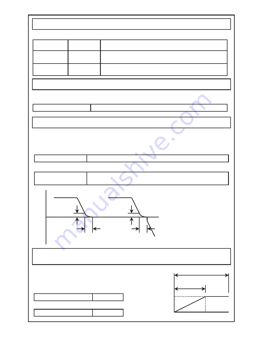
DC BRAKE TIME and DC BRAKE LEVEL(Parameter P12 and P13)
The DC brake can be applied when the inverter output frequency drops below
the stop frequency during ramp-to-stop or when switching between forward run
and reverse run.
[Parameter P12: The DC brake time is set.]
[Parameter P13: The DC brake level is set.]
0 to 100 (Set in increments of 5. The braking force will increase
when a larger value is set.)
Forward
Reverse
Operation frequency
Stop
frequency
(P11)
DC brake time(P12)
[ramp-to-stop]
[Forward run / reverse run]
0.5Hz
DC brake time
fixed to 0.1s
䋪
The frequency for applying the
DC brake is set by parameter
P11 stop frequency.
䋪
The DC brake time when
switching between forward run
and reverse run is fixed to 0.1s.
Used to set the frequency which the inverter output stops when the inverter
decelerate to a stop.
STOP FREQUENCY(Parameter P11)
Data setting range (Hz)
Data setting range (Hz)
Data setting range (Hz)
Data setting range(s)
Data setting range
0.5 to 60 (Set in 0.1Hz increments)
STOP MODE(Parameter P10)
Used to select whether to ramp-to-stop or coast-to-stop when stopping the inverter.
Data
setting value
Details
Explanation of operation
0
The frequency is decelerated by the stop signal according
to the deceleration time, and then the motor stops.
1
The inverter output is shut off immediately by the stop
signal.
ramp-to-stop
coast-to-stop
MAX. OUTPUT FREQUENCY and BASE FREQUENCY
(Parameter P14 and P15)
Used to set the maximum output frequency
and base frequency.
(These parameters are valid only when
"FF" is set in Parameter P03.)
50.0
WR
250
[Parameter P14: The max. output frequency is set.]
[Parameter P15: The base frequency is set.]
45.0
WR
250
Output frequency (Hz)
Base frequency (P15)
0
100
Max. output frequency
(P14)
㩿䋦㪀
Output voltage
46
000
g
0.1 to 120 (The brakes are not applied when 000 is set.)


