20
Palmgren Operating Manual & Parts List
84315
OPERATION (CONTINUED)
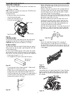
USE OF SANDING DRUMS
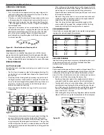
Refer to Figure 77.
Standard sanding drums are usually rubber cylinders which can be
expanded to hold an abrasive sleeve in place. Similar cylinders,
turned on the lathe and covered with abrasive paper, will be ade-
quate for the job. These have the advantage that special sizes,
tapers, etc. can be made. Adhesive papers must be glued to the
cylindrical surface precisely and completely.
The drum is used mainly for sanding the edges of curved work.
•
The squareness of the edge of the work can be best retained by
using a simple form of vertical fence as shown.
•
The standard sanding drums are commonly made with a
threaded hole to fit the lathe drive spindle.
•
To guard against loosening of the taper shank while the drum
is in operation, it is advisable to support the free end, using
either a ballbearing or plain 60° center in the tail stock.
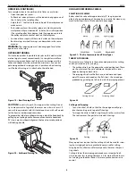
USE OF WOOD CHUCKS FOR SANDING
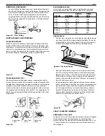
Quick-acting chucks can be very useful for sanding operations on
duplicate production parts. The chuck is made slightly oversized,
and a piece of rubber hose (for small parts) is inserted in the recess
to grip the workpieces.
M
MA
AIIN
NT
TE
EN
NA
AN
NC
CE
E
WARNING:
Make certain that the unit is disconnected from power
source before attempting to service or remove any component.
CLEANING
Keep machine and workshop clean. Do not allow sawdust to accu-
mulate on the tool. Keep centers clean.
Be certain motor is kept clean and is frequently vacuumed free of
dust.
Use soap and water to clean painted parts, rubber parts and plastic
guards.
LUBRICATION
The shielded ball bearings in this tool are permanently lubricated
at the factory. They require no further lubrication.
KEEP TOOL IN REPAIR
•
If power cord is worn, cut, or damaged in any way, have it
replaced immediately.
•
Replace any damaged or missing parts. Use parts list to order
parts.
Any attempt to repair motor may create a hazard unless repair is
done by a qualified service technician. Repair service is available at
your nearest Palmgren store.
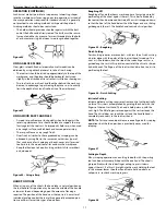
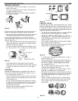
REPLACING WORN FAN BELT
Refer to Figure 79.
•
Remove upper rear cover (1 screw).
•
Remove top cover (4 screws).
•
Remove front cover.
•
Remove and replace belt.
•
Assemble in reverse order.
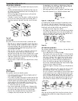
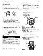
REPLACING WORN VARIABLE SPEED BELT
Refer to Figures 79 and 80.
NOTE:
a mechanical jaw puller and snap ring pliers are required to
perform this operation.
•
Remove upper rear cover (1 screw).
•
Remove top cover (4 screws).
•
Remove rear cover (4 screws).
•
Remove snap ring from drive shaft.
•
Remove 4 socket head bolts from plate.
•
Using puller, remove plate, bearing and pulley.
•
Remove snap ring, cap, spring and pulley from spindle shaft.
CAUTION:
Cap is spring loaded and in tension.
•
Remove and replace belt.
•
Assemble in reverse order.
Figure 80
Top Cover
Rear Cover
Front Cover
Figure 79
Upper Rear
Cover
Drive Shaft
Spindle
Plate
Cap
Figure 77
Figure 78


