background image

14

Palmgren Operating Manual & Parts List

84315

OPERATION (CONTINUED)

MAKING LONG CONVEX CUTS

First, turn work down to approximate size, using sizing cuts (as
required) to determine various diameters. Finish cuts can then
be made with either skew or gouge.

If the skew is used, the principles of the operation are the same
as those employed in cutting a bead – except that the curve is
longer and may be irregular. Use the extreme heel throughout
– start at longer end of curve (if curve is irregular) and progress
toward steeper end.

If gouge is used, make cut in the same direction. Start with the
handle well back of point – swinging handle in the direction of
tool travel to overtake the point, if necessary, when the steep
part of the curve is reached. Object is to have the extreme
point doing the cutting throughout with the bevel as tangent
to curve as possible.

MAKING LONG TAPER CUTS

Long taper cuts are made like long convex cuts, with the skew or
gouge. However, the angle between the cutting edge and handle is
kept constant during the entire cut.The handle is not swung around.

Always cut downhill. Do not cut too deeply at the center of the taper.

SPINDLE TURNINGS

PLOTTING THE SHAPE

Once the basic cuts have been mastered, you are ready to turn out
finished work.

The first step is to prepare a plan for the proposed turning. This
can be laid out on a suitable sheet of paper. The layout should
be to full size.

Next, prepare the turning stock by squaring it up to the size of
the largest square or round section in your plan. The stock can
be cut to the exact length of the proposed turning. However, in
most cases, it is best to leave the stock a little long at one or
both ends to allow for trimming.

Mount the stock in the lathe and rough it off to a maximum-
size cylinder.

Now, project your plan onto the turning by pencil marking the
various critical dimensions along the length of the spindle.
These dimensions can be laid out with an ordinary ruler or by
using a template. Make the pencil marks about 

1

/

2

long so they

will be visible when the work is revolved under power. The lines
can be quickly traced around the spindle by touching each line
with the pencil.

After marking, use the parting tool to make sizing cuts at all of
the important shoulders. When learning, you will find it best to
make sizing cuts to accurately plot the various diameters.
Experienced wood workers can manage with fewer such cuts at
the important shoulders.

Plan each sizing cut so that it is in waste stock and make each
cut deep enough so that there will be just enough wood left
under the cut for the finishing process.

Once the sizing cuts have been completed, rough-out the
excess wood with a gouge. Then, proceed with the finishing
process by making the various types of cuts required.

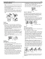
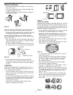
RECOMMENDED SPEED

Always follow recommended speed to do spindle turning depend-
ing upon the size and length of workpiece.

DUPLICATE TURNINGS

Identical turnings require great accuracy when plotting the work
and performing the various cuts. Many methods have been
devised to aid in perfecting the work.

Use of Patterns

Professional workers generally use a pattern or layout board. This is
a thin piece of wood or cardboard upon which is drawn a full-size
half section of the turning. The contour of the finished surface is
drawn first. Then, the diameters at various critical points are drawn
to scale as vertical lines intersecting the contour line.

By placing the pattern against the roughed-out cylinder, you
can quickly mark the various points of the critical diameters.

To make each sizing cut, use outside calipers and set these by
actually measuring the length of the vertical lines on the pat-
tern which represent the diameters desired. Make the sizing cut
down to the proper diameter by using the calipers to deter-
mine when the cut is finished.

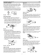
After making the sizing cuts, hang the pattern behind the lathe
where it will serve as a guide for completion of the workpiece.

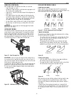
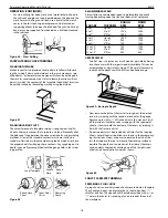
Figure 48 – Chisel Inclined in Direction of Cut

Figure 50

SQUARE

1 to 2

1 to 2

1 to 2

2 to 4

2 to 4

2 to 4

4

Plus

4

Plus

4

Plus

LENGTH

1 to 12

to 24

to 38

1 to 12

to 24

to 38

1 to 12

to 24

to 38

ROUGH
RPM

1300
1100
1000
1000
900
700
800
600
400

FINISH
RPM

2000
2000
2000
1800
1600
1400
1400
1100
800

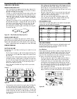
Tenon

Diameters

1

1

/

4

1

1

/

2

1

1

/

2

1

1

/

4

1

3

/

4

1

7

/

8

1

11

/

16

1

1

/

4

1

9

/

16

14

1

/

4

2

1

/

16

2

1

/

4

2

1

/

4

2

1

/

4

2

1

Sizing Cuts

Figure 49

3

1

/

8

Summary of Contents for 84315

Page 1: ...l l p pa ar rt ts s l li is st t 8 84 43 31 15 5 1 15 5 V VA AR RI IA AB BL LE E S SP PE EE ED D W WO OO OD D L LA AT TH HE E Read carefully and follow all safety rules and operating instructions befo...

Page 2: ...Remember that being careless for even a fraction of a second can result in severe personal injury BE PREPARED FOR JOB Wear proper apparel Do not wear loose clothing gloves neck ties rings bracelets o...

Page 3: ...orkpiece and start with a new piece of wood Use extra care when turning wood with twisted grain or wood that is twisted or bowed it may cut unevenly or wobble excessively KNOW YOUR CUTTING TOOLS Dull...

Page 4: ...the line cord to make sure that the plug is in good condition and that the insulation has not been damaged dur ing transit I IN NS ST TA AL LL LA AT TI IO ON N Refer to Figures 7 12 MOUNTING LATHE TO...

Page 5: ...istance for electrical shock WARNING Do not permit fingers to touch the terminals of plug when installing or removing from outlet Plug must be plugged into matching outlet that is properly installed a...

Page 6: ...er supply See wiring diagram Figure 12 for wiring instructions O OP PE ER RA AT TI IO ON N Refer to Figures 13 78 WARNING Operation of any power tool can result in foreign objects being thrown into th...

Page 7: ...r and drive the spur center into the other end of the wood Make sure the spurs are in the saw cuts Remove the spur center Make sure the centers and the hole in the spindle and the tail stock ram are c...

Page 8: ...by pulling up on locking handle Remove pin and rotate headstock 90 Insert pin at outboard alignment hole and secure headstock with locking handle USING WOODWORKING CHISELS SELECTION OF CHISELS Better...

Page 9: ...g edge will con tinue to dig deeper into the work It will dig in until the bite becomes so deep that your hands have difficulty holding the chisel then the improperly supported chisel will begin to bo...

Page 10: ...e handle bevel side down Keep the base of the bevel against the work It is good practice is to place the skew well over the work pull it back until the edge begins to cut then swing the handle into po...

Page 11: ...handle This position may be near the middle of the handle or towards the end depending upon the amount of leverage required The position of the hand near the tool rest is a matter of individual prefe...

Page 12: ...zing cuts are useful to establish approximate finished size diame ters at various points along a workpiece The work can then be turned down to the diameters indicated and be ready for finishing Diamet...

Page 13: ...edge begins to cut roll skew in the direction of the vee so that the exact portion of the edge which started cutting will travel in a 90 arc down to bottom of the vee Upon reaching bottom of the vee t...

Page 14: ...be quickly traced around the spindle by touching each line with the pencil After marking use the parting tool to make sizing cuts at all of the important shoulders When learning you will find it best...

Page 15: ...ining on workpiece CUTTING DOWELS Dowels of any size can be turned quickly with the simple jig shown If the stock is prepared as a split or quartered turning half round and quarter rounds will be prod...

Page 16: ...step is to remove as much wood as possible by boring into the center with the largest wood bit available This can be accomplished as illustrated in Figure 59 Be careful to measure in advance the depth...

Page 17: ...and it is turned in the usual manner All surfaces are cut except the back side which is against the mounting block The work is then removed from the mounting block An auxiliary chuck of softwood is no...

Page 18: ...ight fit of the lid can be relieved by sanding the lip of the body SEGMENTED TURNINGS Segmented bowls and boxes are exceptionally attractive and this method of preparing wood stock is more economical...

Page 19: ...duced all having a distinctive surface pattern preformed tools will speed the work and assure uniformity Patterns like those illustrated can be created by grinding thin 020 to 010 gauge aluminum strip...

Page 20: ...omponent CLEANING Keep machine and workshop clean Do not allow sawdust to accu mulate on the tool Keep centers clean Be certain motor is kept clean and is frequently vacuumed free of dust Use soap and...

Page 21: ...f round 2 Workpiece has too much wobble 3 Operator using bad technique 4 Cutting motion is against the grain of the workpiece 5 Workpiece is too long and thin workpiece is deflected by tool pressure W...

Page 22: ...1 60 19 21 21 20 20 22 36 80 83 79 78 77 28 69 69 26 27 29 31 34 72 30 32 33 47 40 43 43 50 51 81 59 49 45 57 58 52 53 54 55 56 73 74 75 76 70 70 71 46 42 41 7 8 8 8 38 39 37 37 35 67 68 23 2 1 1 3 12...

Page 23: ...djusting Rod 18036 00 1 42 Retainer 18037 00 1 Ref No Description Part No Qty 43 6 1 0 x 12mm Flat Head Screw 08567 00 4 44 5 0 8 x 6mm Set Screw 03069 00 1 45 Gear 18038 00 1 46 5 0 8 x 10mm Flat Hea...

Page 24: ...63 64 76 77 62 61 60 19 21 20 22 36 65 66 28 69 26 27 29 31 34 72 30 32 33 47 40 43 50 51 59 49 45 59 57 58 58 52 53 53 54 55 56 73 74 75 70 71 46 42 41 7 8 38 39 65 37 35 67 68 23 2 1 3 12 12 18 17...

Page 25: ...ain 18084 00 1 33 Rear Cover 18085 00 1 34 Upper Rear Cover 18086 00 1 35 5 0 8 x 12mm Socket Head Bolt 1 36 Spacer 18087 00 1 37 Index Pin Lever 18088 00 1 38 5 0 8 x 30mm Socket Head Bolt 2 39 Block...

Page 26: ...26 Palmgren Operating Manual Parts List 84315 NOTES...

Page 27: ...27 Palmgren Operating Manual Parts List 84315 NOTES...

Page 28: ...charge To order parts for a non warranty repair please contact your preferred Palmgren distributor To obtain the names of Palmgren distributors or to arrange warranty return please call Palmgren Stee...

Reviews: