2.5.5 J6 Encoder/Step and Direction Input Connection
Introduction
Connector J6 accepts encoder quadrature inputs for A, A, B, B, Z
and Z which can be used for electronic gearing, encoder position
verification, and stall detection.
Alternatively, a program variable can be set to switch the encoder
inputs to external step and direction inputs. These converted
inputs are DIR, DIR , STEP, and STEP.
Encoder
requirement
The encoder must provide quadrature differential, line driver
outputs. The receiver IC is an SM75175.
Input table
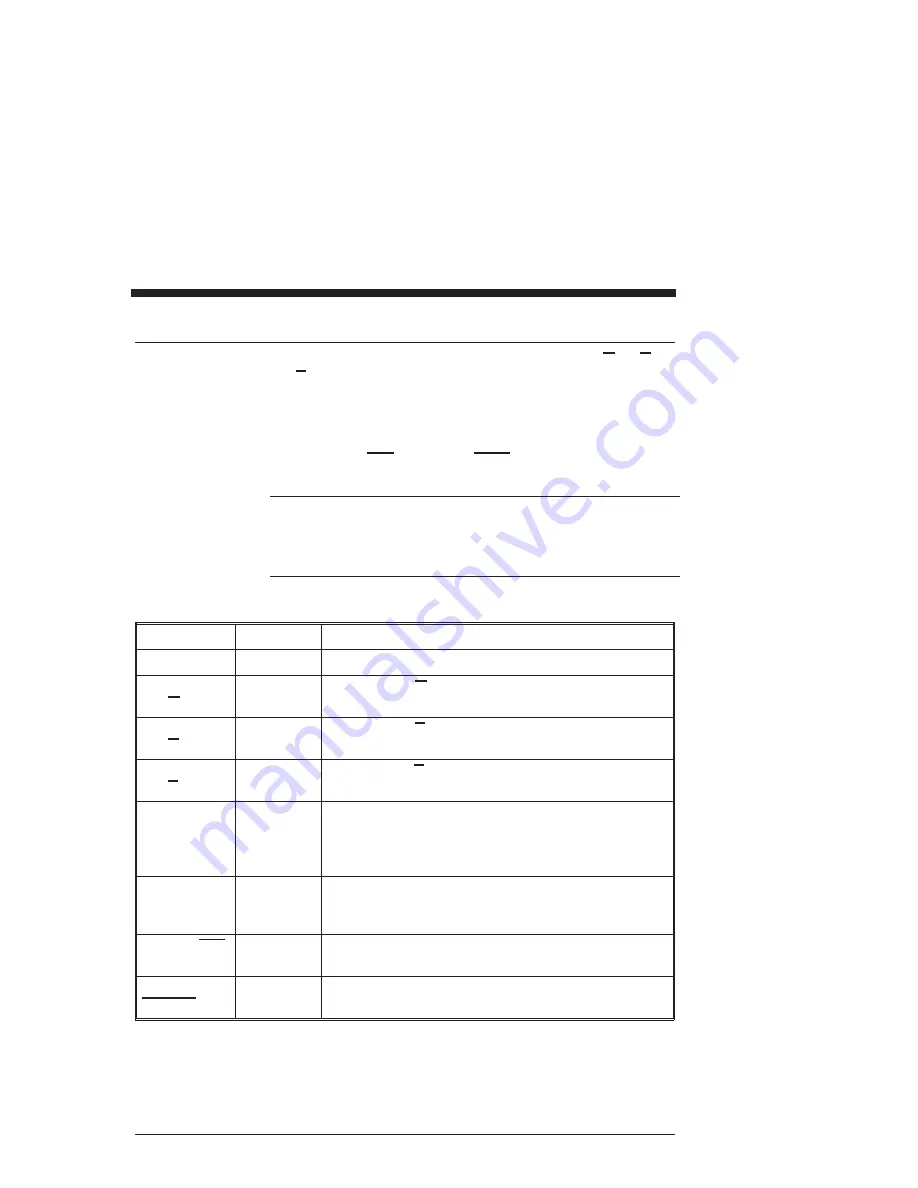
The following table lists the inputs on connector J6:
Input
Pin Number Explanation
No connect
J6-1
This pin is not used.
Channel A
and A
J6-2 and
J6-3
For the A and A quadrature encoder inputs.
Channel B
and B
J6-4 and
J6-5
For the B and B quadrature encoder inputs.
Channel Z
and Z
J6-6 and
J6-7
For the Z and Z quadrature inputs.
+ 5 V dc
J6-8
To provide power for the encoder. The maximum
allowable load on this pin must be an amount that,
when added to the load on pins J3-4 and J7-7, totals to
less than 450 mA.
+5 V return
J6-9
To provide 5 volt ground.
Note: If using external power, you must connect the
power supply ground here.
Step and step
J6-2 and
J6-3
Alternative input used with STEP.DIR.INPUT = 1 to
input step signals for external control.
Direction and
direction
J6-4 and
J6-5
Alternative input used with STEP.DIR.INPUT = 1 to
input direction signals for external control.
Rev F
5345/5445 Installation and Hardware Manual
2 - 33
Artisan Technology Group - Quality Instrumentation ... Guaranteed | (888) 88-SOURCE | www.artisantg.com


