21
Remove all three sprockets and chains. Thoroughly
clean and inspect any parts that will be re-used for signs
of damage and/or excessive wear. Replace worn parts
as required.
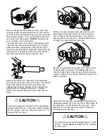
Install new sprockets and chain. When installing inter-
mediate and final drive sprockets, make sure they turn
smooth and freely on their bushings. Be sure the retain-
ing ring for the primary sprocket is fully seated in its
groove. Install the two spacers onto shaft of the inter-
mediate sprocket. Apply a coating of oil soluble grease
to hold them in place until the cover is installed.
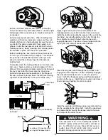
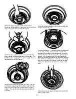
Before installing the cover, pull out the pull tube as far
as it can go, and rotate the drum slightly. This will hold
the pull tube in its extended position, making it much
easier to install the retaining ring after the piston is
installed later.
Thoroughly clean the mating surfaces on the chain case
and cover. Apply a small, even bead (approx. 3/16 in.)
of Dow 732 or equivalent silastic sealant to the flange of
the cover and install the cover onto the chain case.
Install all capscrews and lockwashers in the flange of
the case and evenly torque them. Install the remaining
capscrew and lockwasher in the center of the cover.
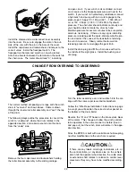
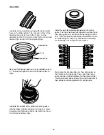
Be sure the thrust washer is in place on the freespool
“pull tube”
Pull Tube
Thrust
Washer
Primary
Sprocket
Chain Case
Cover
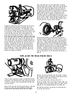
Apply a light coat of winch oil to the outside of the
freespool piston and install it into the chain case cover.
Install the retaining ring into the groove in the end of the
“pull tube”, securing the piston to the tube. Rotate the
drum slightly and push the pull tube into the winch,
engaging the drum. The drum is now engaged with the
winch gear train and will not be able to rotate.
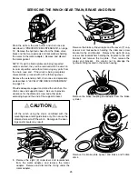
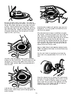
Insert the long drive shaft through the “pull tube” and
engage the internal splines. When completely engaged,
the driveshaft will extend 1 3/4 in. (44 mm) past the
cover. Install the freespool spring and the bearing/seal
carrier into the cover. Install the two countersunk socket
head capscrews holding the carrier in place.
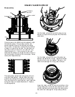
Install the extension shaft/torque tube assembly and fas-
ten the coupling to the drive shaft. Install the capscrews
and lockwashers securing the torque tube to the cover
and torque to the correct value.
The capscrews used in the coupling are Grade 8.
DO NOT replace either of them with a soft bolt or
pin. A soft bolt or pin may shear off and cause a
sudden loss of load control which may result in
property damage, personal injury or death.
CAUTION
WARNING
!
!
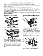
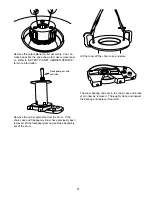
Location of O-rings and back-
up rings on freespool piston.
O-rings
Backup ring
Backup ring
Summary of Contents for Braden BP200
Page 46: ......


