8
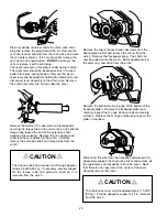
opening toward the diamond screw. Disengage the dia-
mond screw by rotating the lever on the chain case, 90o
toward the front of the winch. Using the handwheel on
the motor end of the winch, turn the diamond screw in the
same direction as the winch hauls in cable until the roller
bracket is at the flange where the cable will be anchored.
The pawl should be just starting to enter the turnaround
area of the screw. Re-engage the diamond screw.
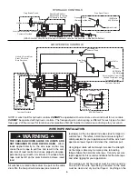
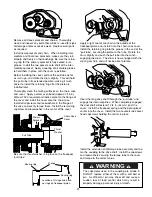
Thread the wire rope through the spring loaded rollers
and anchor it to the winch drum. Refer to the figures on
the previous page for additional information. When
spooling cable onto the drum, the roller bracket should
lag behind where the rope is laying onto the drum by 1/2
of a rope diameter. Re-adjust the position of the roller
assembly, if needed, after beginning to spool wire rope
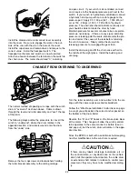
onto the drum. The diamond screw levelwind alone does
not assure smooth even spooling of cable onto the drum.
A light load (approx. 200 to 400 LB , 90 to 180 kg) should
be maintained on the cable to assist even spooling.
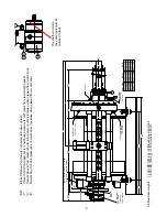
DIMENSIONAL DRAWINGS AND SPECIFICATIONS
HAUL-IN
DIAMOND SCREW
IS IN THIS POSITION
ENGAGED
1.125
FREESPOOL
PORT
SAE -4 ORB
(7/16 - 20 THD)
35.52
(902)
22.53
(572)
17.66
(449)
14.96
(380)
12.98
(330)
29.00
(737)
11.87
(302)
16.87
(429)
11.38
(289)
22.76
(578)
DISENGAGED WHEN HANDLE
Internal brake effective both directions
Minimum 150 psi (1,030 kPa), above motor outlet pressure, required to shift motor to high speed
Maximum allowable pressure at motor shift port - 2,500 psi (17,200 kPa)
Shaft end motor case drain must be drained to tank
Layer
LBS
kN
FPM
MPM
LBS
kN
FPM
MPM
FT
M
1
20,000
89.0
44
13
9,860
43.9
88
27
148
45.1
2
18,440
82.0
48
15
9,090
40.4
96
29
309
94.2
3
17,110
76.1
52
16
8,440
37.5
104
31
482
147
4
15,960
71.0
55
17
7,870
35.0
111
34
668
204
5
14,950
66.5
59
18
7,370
32.8
119
36
866
264
6
14,060
62.5
63
19
6,930
30.8
126
38
1,077
328
7
13,270
59.0
67
20
6,540
29.1
134
41
1,301
397
8
12,570
55.9
70
21
6,200
27.6
141
43
1,537
469
Rope Capacity
9/16 in. (14 mm)
Low Speed
Line Pull
Line Speed
High Speed
Line Pull
Line Speed
2 speed motor displacement is
21.2/10.6 cu in. (347/173 cu cm).
Performance based on:
2,500 psi (17,200 kPa) at
30 gpm (114 LPM)
Other Rope Capacities:
1/2 in. - 2,226 ft (678 M)
7/16 in. - 2,769 ft (844 M)
NOTE: Continuous operation at
high speeds and loads may
require the use of an oil cooler in
the hydraulic system to maintain
acceptable oil temperature.
Dimensions shown are
inches (millimeters)
Summary of Contents for Braden BP200
Page 46: ......


