4
BASIC OPERATION
This emblem is used to warn against potential
or unsafe practices which COULD result in
personal injury, and product or property dam-
age if proper procedures are not followed.
CAUTION
This emblem is used to warn against unsafe
practices which COULD result in severe per-
sonal injury or death if proper procedures are
not followed.
CAUTION
WARNING
!
!
25. Keep hydraulic system clean and free from contami-
nants at all times.
26. Use correct anchor for the wire rope size being
installed.
27. Do not use knots to secure or attach wire rope.
28. The BRADEN designed wire rope anchors are capa-
ble of supporting the rated load when installed prop-
erly. For additional safety, ALWAYS maintain a mini-
mum of five (5) wraps of wire rope on the drum. It
is recommended that the last five (5) wraps of wire
rope be painted bright red to serve as a visual
reminder.
29. Never allow anyone to stand under a suspended
load.
30. Avoid sudden “shock” loads or attempt to “jerk” a
load free. This type of operation may cause heavy
loads in excess of rated capacity, which may result
in failure of the wire rope and/or winch.
Safety and informational callouts used in this manu-
al include:
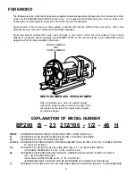
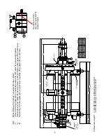
DESCRIPTION OF WINCH
The BRADEN BP200 winch consists of the following
sub-assemblies:
1.
Motor and brake valve block with cartridges
2.
Load holding friction brake assembly
3.
Drum drag brake
4.
Two stage planetary gear set
5.
Cable drum, closure and bearings
6.
Level wind system
7.
Extension shaft
8.
Drum clutch
The BP200 winch is supplied with provisions for either
air or hydraulically operated drum drag and drum clutch
controls. Refer to the “EXPLANATION OF MODEL
NUMBER” to determine the type of control for your
winch. Refer to “WINCH INSTALLATION” for control cir-
cuits.
NOTE: A winch built for air control CANNOT be operat-
ed hydraulically, or vice-versa, without changing the
clutch spring. Consult the BRADEN Service Department
for details.
THEORY OF OPERATION
When the winch is “at rest” with no hydraulic or air pres-
sure applied, the load holding brake is fully applied by
spring pressure, preventing the drum, drive train gears
and motor from rotating. The drum clutch is fully
engaged by spring pressure, and the drum drag brake is
not applied.
BASIC WINCH OPERATION
The winch is built with a solid hub between the input
shaft and the brake discs, which means the load holding
friction brake must be released before the winch will
rotate in either direction. When hydraulic pressure is
applied to either the haul-in or pay-out port, it is routed
to the brake release piston and blocked from flowing
through the motor. The motor cannot rotate until suffi-
cient pressure is present to open the brake valve car-
tridge. The load holding brake within the winch will
completely release at a pressure less than that required
to open the cartridge and allow the motor to rotate.
Once the cartridge is open, the planetary gears, cable
drum and extension shaft will rotate at a speed propor-
tional to the flow of oil to the motor. When the control
valve is returned to the neutral position, pressure will
drop and the cartridge will close, stopping the motor and
the load. As the pressure drops further, the internal load
holding brake is applied by spring pressure, securely
holding the load. In this normal type of operation, the
friction brake receives very little wear. All the heat gen-
erated by stopping a load is absorbed by the hydraulic
oil where it can be readily dissipated.
DRUM CLUTCH
The drum clutch is spring applied, and air or hydraulical-
ly released. The release mechanism is a mechanical
disengagement of the drum from the drive train. The
Summary of Contents for Braden BP200
Page 46: ......


