5
winch is equipped with an electrical switch that will light
the red “WINCH DISENGAGED” lamp on the freespool
panel whenever the drum is disengaged from the drive
train. In this position, wire rope can be pulled from the
drum by hand, provided the drum drag brake is not acti-
vated. The extension shaft/capstan drive can also be
operated in this mode without the cable drum rotating.
To disengage the drum, the winch should be stopped
and there should be no load on the cable drum. To
engage the clutch, the drum may have to be rotated
slightly by hand to align the internal splines. When the
clutch is fully engaged, the green “WINCH ENGAGED”
lamp on the freespool panel will be lit.
DRUM DRAG BRAKE
The BP200B has two (2) drag brake cylinders, (one (1)
on the BP200). These can be either air or hydraulically
operated. Their purpose is to control drum movement
when the winch is in freespool mode with the drum dis-
connected from the drive train. They are not designed
nor intended to hold a load. The amount of drag they
provide can be easily adjusted using one of the circuits
shown in the “INSTALLATION” section of this manual.
All hardware for these control circuits is customer pro-
vided.
LEVEL WIND
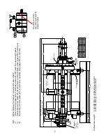
The BP200 winch is equipped with a level wind system
to ensure smooth even spooling of wire rope onto the
drum. The speed of the tension roller assembly in rela-
tion to the cable drum speed is specific to each size
wire rope. In order to change wire rope size, the chain
and sprockets driving the level wind diamond screw
must be changed. Refer to “LEVEL WIND DRIVE
GROUP CONVERSION PARTS” for additional informa-
tion. The system is provided with a manual disconnect
and hand wheel on the diamond screw. The disconnect
lever is located on the side of the winch opposite the
motor. With the lever pointing down in a vertical posi-
tion, the diamond screw is engaged. Rotating the lever
90o toward the front of the winch disengages the screw
and allows it to be rotated using the hand wheel on the
opposite end, near the motor. This feature is used to
properly align the tension roller assembly with the wire
rope on the drum. It may be necessary to perform this
alignment occasionally to compensate for normal wire
rope stretch and/or wear, or when new wire rope is
installed.
INSTALLATION
GENERAL REQUIREMENTS
The winch should be mounted with the centerline of the drum in
a horizontal position. Typically, the base will be fastened directly
to the frame of the vehicle.
When mounting the winch, the method of attachment must be
capable of withstanding the full 20,000 pound line pull.
It is important that the winch be mounted on a surface that will
not flex when the winch is in use, since this could bind the work-
ing parts of the winch. Also, be sure the winch is mounted on a
flat surface. If necessary, use shim stock to insure proper
mounting. The mounting surface should be flat or -.020
inches (.5 mm).
Hydraulic lines and components that operate the winch should
be of sufficient size to assure minimum back pressure at the
winch. Back pressure should not exceed 100 psi (690 kPa) for
maximum motor seal life. 150 psi (1,030 kPa) is the maximum
peak intermittent allowable back pressure. A motor case drain
from the shaft end drain port to tank is required.
The winch directional control valve must be a three-position,
four-way valve with a motor spool having both work ports open
directly to tank, when the valve is in the center position.
The extension shaft must be attached to the end of the winch
opposite the motor. The shaft may be connected to the cou-
pling in one of two positions, allowing a 2 inch adjustment in
length.
The hydraulic oil filter should have a 10 micron nominal rating
and be a full-flow type.
High quality hydraulic oil is essential for satisfactory performance
and long hydraulic system component life.
Oil having 150 to 330 SUS viscosity at 100°F (38°C) and vis-
cosity index of 100 or greater will give good results under normal
temperature conditions. The use of an oil having a high viscosity
index will minimize cold-start trouble and reduce the length of
warm-up periods. A high viscosity index will minimize changes in
viscosity with corresponding changes in temperature.
Maximum cold weather start-up viscosity should not exceed
5000 SUS with a pour point at least 20°F lower than the mini-
mum temperature.
Under continuous operating conditions the temperature of the oil
at any point in the system must not exceed 180° F (82° C).
120-140° F (49 - 60° C) is generally considered optimum.
In general terms; for continuous operation at ambient tempera-
tures between 50 and 110° F (10 to 43° C), use SAE 20W; for
continuous operation between 10 and 90° F (-12 to 32° C), use
SAE 10W; for applications colder than 10°F, contact the
BRADEN Service Department. The use of multi-viscosity
oils is generally not recommended.
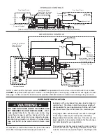
Refer to the following drawings for winch control circuit,
drag brake circuit and freespool circuit.
NOTE: Continuous operation at high speeds and loads
may require the use of an oil cooler in the hydraulic sys-
tem to maintain acceptable oil temperature.
Summary of Contents for Braden BP200
Page 46: ......


