OWC Jupiter Mini-SAS
SySteM MAintenAnCe
sYsTeM MaInTenanCe
3.1 REPLACING COMPONENTS
3.1.1 Power supply Unit (PsU) Modules
The Jupiter Expander Rack 835 storage system comes with a hot swappable 1+1 redundent power supply,
meaning the Jupiter unit can tolerate one PsU module failing and can be serviced while powered on. When both
PsU modules are healthy the power load is automatically balanced between them. In the event of a PsU module
failure, an alarm will sound and the fan system status light on the front of the Jupiter unit will be red. To replace
the problematic PsU module:
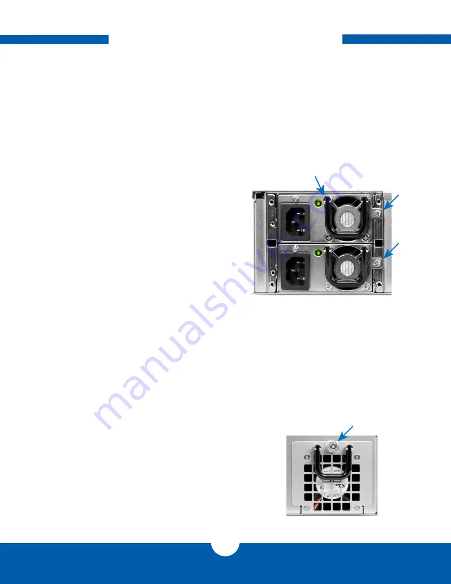
1. Identify the failed PsU module by seeing
which module does not have its leD lit.
2. loosen securing screw, using a screwdriver if
necessary.
3. after loosening the screws, pull the PsU
module out using the black handle. If it does
not slide out, try loosening the securing screw
more and pulling again.
4. after removing the failed PsU module, insert
the new module making sure it is fully seated
inside the PsU.
5. Hand-tighten the securing screw. a flathead
screwdriver can be used but it is not
necessary. If using a screwdriver, do not over
tighten the screw as it may be necessary to
loosen using fingertips only.
6. after securing the new PsU module in place,
plug in the power cord and turn the unit on if
it is not already.
3.1.2 fans
The Jupiter expander Rack 835 storage system has hot swappable fan modules. In the event of a fan failure the fan
system status light on the front of the Jupiter will be red. To replace a problematic fan module:
1. Identify the failed fan by feeling and looking at
each fan module. often the fan module will
not be spinning at all or as fast as the other
healthy one. You can also use the Jupiter
Command Center application to identify the
failed fan.
2. Using fingers or a Phillips screwdriver, loosen
the thumbscrew on the failed fan module as
pointed to in
Figure 3.1.2a
.
Figure 3.1.1a
Securing
screw
Securing
screw
Removal
handle
Figure 3.1.2a
Thumbscrew
13


