background image

The Connection Wizard opens and guides you through the process of establishing a connection.

5)  Follow the subsequent instructions on the screen.
6)  After the Bluetooth PIN is entered, a connection to the component is established.

While the connection is being established, 3 beep signals sound and the 

 symbol appears in the bottom

right corner of the screen.
The 

 symbol is displayed when the connection has been established.

Once the connection has been established, the data are read from the component. This process may take up to
a minute.
Then the main menu appears with the name of the connected component.

INFORMATION

After the initial connection to the component has been established successfully and when the Bluetooth function
is activated, the app will connect automatically each time it is started. No further steps are required.

INFORMATION

After activating the "visibility" of the component (briefly pressing the   button), the component can be recognised
by another device (e.g. smartphone) within 2 minutes. If registration or establishing the connection takes too long,
the  process  of  establishing  a  connection  is  cancelled.  In  this  case  the    button  on  the  control  panel  must  be
briefly pressed again.

INFORMATION

If the connection to the component could not be established or the connection process is terminated, reset the
component by connecting and disconnecting the battery charger.

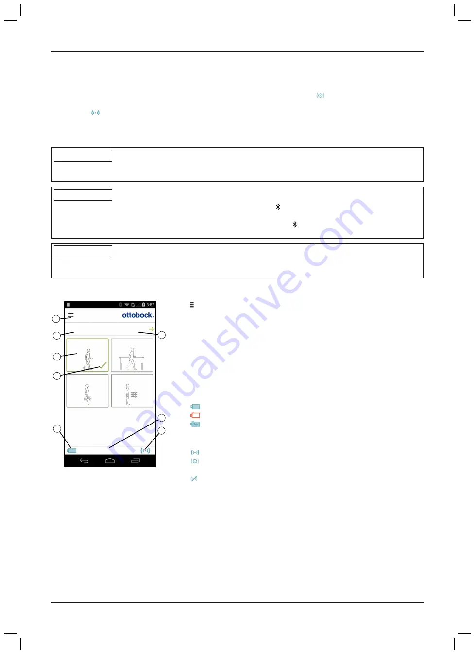
9.3 Control elements for cockpit app

1

2

3

4

5

6

7

8

1. Basic Mode

2. Training mode

3. Freeze position

4. User defined

Product

change

1. Basic Mode

100%

1.

 Access the navigation menu (see Page 90)

2. Name  of  the  component.  This  name  can  only  be  changed  using  the

adjustment app.

3. If connections to more than one component have been saved, you can

switch between the saved components by tapping the 

change

 item (see

Page 90).

4. MyModes configured with the adjustment app.

Switching the mode by tapping the corresponding symbol and confirm­
ing by tapping "

OK

".

5. Currently selected mode
6. Charge level of the component.

 Component battery fully charged

 Component battery empty
 Component battery is being charged

The current charge level is also displayed in %.

7. Display and name of the currently selected mode (e.g. 

1. Basic Mode

)

8.

 Connection to component has been established
 Connection to component has been interrupted. The app is attempt­

ing to re-establish the connection automatically.

 No existing connection to the component.

89

C-Brace joint unit 17KO1=*

Cockpit app

Summary of Contents for 17KO1 Series

Page 1: ...Gebrauchsanweisung Fachpersonal 5 Instructions for use qualified personnel 61 C Brace joint unit 17KO1...

Page 2: ...bruiksaanwijzing is behalve in gedrukte vorm ook in diverse andere talen bijgevoegd op cd zie de achterzijde van de oms lag Een gedrukte gebruiksaanwijzing in de gewenste taal kunt u kosteloos bestell...

Page 3: ...Ottobock Healthcare Products GmbH Brehmstra e 16 1110 Wien Austria Service admin vienna ottobock com Fax 43 1 526 79 85 3 C Brace joint unit 17KO1...

Page 4: ...4 C Brace joint unit 17KO1...

Page 5: ...eise zur Verwendung eines mobilen Endger ts mit der Cockpit App 4 12 20 Lieferumfang und Zubeh r 5 20 Lieferumfang 5 1 20 Zubeh r 5 2 21 Akku laden 6 21 Netzteil und Ladeger t anschlie en 6 1 21 Ladeg...

Page 6: ...hese aufgebaut mit Bewegung im Kn chelgelenk 10 3 6 2 41 Treppe hinauf gehen 10 3 7 42 Rampe hinauf gehen 10 3 8 42 Rampe hinab gehen 10 3 9 42 Flache Stufen hinab gehen 10 3 10 42 Niederknien 10 3 11...

Page 7: ...Technische Daten 16 51 Anh nge 17 54 Angewandte Symbole 17 1 54 Betriebszust nde Fehlersignale 17 2 54 Statusanzeige am Bedienfeld 17 2 1 54 Fehlermeldungen beim Verbindungsaufbau mit der Cockpit App...

Page 8: ...formationen zur Montage der Gelenkeinheit entnehmen Sie dem Kapitel Herstellung der Gebrauchsf higkeit siehe Seite 24 Nehmen Sie das Produkt nur gem den Informationen in den mitgelieferten Begleitdoku...

Page 9: ...Beugewiderstand des Produkts beeinflusst Die Sensordaten werden 100 mal pro Sekunde aktualisiert und ausgewertet Dadurch wird das Verhalten des Pro dukts dynamisch und in Echtzeit der aktuellen Bewegu...

Page 10: ...t zul ssig 3 3 Indikationen Einseitige oder beidseitige Beinparese oder schlaffe L hmung ausgel st durch z B Post Polio Syndrom trau matische Parese inkomplette Querschnittsl hmung Ausschlaggebend sin...

Page 11: ...stecker oder Ladeger t nicht Setzen Sie Netzteil Adapterstecker oder Ladeger t keinen extremen Belastungen aus Ersetzen Sie sofort besch digte Netzteile Adapterstecker oder Ladeger te VORSICHT Nichtbe...

Page 12: ...saustritt Verwenden Sie zum Transport nur die Transportverpackung VORSICHT Verschlei erscheinungen an den Produktkomponenten Sturz durch Besch digung oder Fehlfunktion des Produkts Im Interesse der Si...

Page 13: ...n das Produkt Keine einwandfreie Ladefunktion infolge Fehlfunktion Achten Sie darauf dass weder feste Teilchen noch Fl ssigkeit in das Produkt eindringen HINWEIS Mechanische Belastung des Netzteils La...

Page 14: ...Beenden der Einstellapp wieder zur ckgesetzt werden Zus tzlich ist darauf zu achten dass der Patient mit den vor bergehend ver nderten Einstellungen nicht au erhalb der Reichweite der Bluetoothverbind...

Page 15: ...es Augenmerk bez glich der Passform Weisen Sie den Patienten darauf hin dass die Hautpartien t glich kontrolliert werden sollen Der Pateint sollte auch bei geringf gigen Anzeichen von Hautsch digungen...

Page 16: ...erhalb dieses Raums oder Bereichs lagert Sind Besch digungen des Produkts aufgetreten die auf die Einwirkung eines starken magnetische Feldes zur ckzuf hren sind gibt es keine Reparaturm glichkeit VOR...

Page 17: ...n Aktivit ten mit Spr ngen pl tzlichen Bewegungen oder schnellen Schritt folgen z B Basketball Badminton sportliches Reiten Sorgf ltige Behandlung des Produkts und seiner Komponenten erh ht nicht nur...

Page 18: ...hin Weisen Sie den Patienten darauf hin dass dieser vor Betreten einer Treppe oder Rampe die ge nderte Standphasend mpfung kontrollieren muss VORSICHT Fehlende Unterst tzung des Produkts beim Hinabge...

Page 19: ...icherheitsmodi VORSICHT Nicht aktivierbarer Sicherheitsmodus durch Fehlfunktion infolge Wassereintritt oder mechanischer Be sch digung Sturz durch unerwartetes Verhalten des Produkts infolge ver ndert...

Page 20: ...schen Signalgeber und die Anzeige auf dem mobilen Endger t beach tet werden muss Wenn die Aktivit ten im MyMode beendet sind muss wieder in den Basismodus gewechselt werden HINWEIS Zerst rung des mobi...

Page 21: ...adevorgangs ist keine Umschaltung der MyModes und das ndern von Einstellparametern ber die Cockpit App m glich Nach dem Abstecken des Ladeger ts befindet sich die Orthese in jenem Zustand in dem sie s...

Page 22: ...sie sich vor dem Anste cken des Ladeger ts befand War die Orthese z B vor dem Anstecken des Ladeger ts abgeschaltet ist sie auch nach dem Abstecken des Ladeger ts abgeschaltet Wird das Ladeger t bei a...

Page 23: ...nach dem Dr cken der Taste bei angestecktem Ladeger t wird der aktuelle Ladezustand zus tzlich zu der Anzeige am Ladeger t durch ein animiertes Symbol am Bedienfeld ange zeigt Bedi enfeld Ladeger t A...

Page 24: ...en und mit den 3 langen Schrauben M5x40 anschrauben 4 Die Gelenkeinheit an die Adapterplatte an der Unterschenkelschale anlegen und mit den 3 kurzen Schrauben M5x8 anschrauben 5 Alle Schrauben mit ein...

Page 25: ...nforderungen Die Funktion der Einstellapp C Brace Setup wurde auf Samsung Galaxy Tab A SM T58x unter Android 7 0 ge testet Folgende mobile Endger te und Betriebssysteme werden unterst tzt iOS Apple iP...

Page 26: ...den 3 Auf die Schaltfl che Anmelden tippen Nach der Anmeldung werden f r die L nge und das Gewicht jene Einheiten verwendet die bei der erstma ligen Anmeldung dieses Benutzers konfiguriert und gespeic...

Page 27: ...kann bis zu einer Minute dauern Anschlie end erscheint der Bildschirm zur Eingabe der Patientendaten Abschnitt Mit bereits gespeichertem Passteil verbinden In diesem Abschnitt werden die letzten zwei...

Page 28: ...Unilateral Ist die Orthese Teil einer unilaterlalen Versorgung muss dieser Parameter an gew hlt werden Bilateral Ist die Orthese Teil einer bilateralen Versorgung muss dieser Parameter ange w hlt werd...

Page 29: ...setzt sich der Patient mit an den Armlehnen abgest tzten H nden in einen Stuhl Er l sst sich in das Produkt sinken und sp rt dabei die sichernde Wirkung des Beugewiderstands Feineinstellung Den Patie...

Page 30: ...en Das blockierte Gelenk kann nun in Beugerichtung belastet werden Manuelle Sperre des Gelenks aufheben Die manuelle Stehfunktion wird durch Streckung des Knies oder durch eine Repositionierung des Be...

Page 31: ...Standphase h lt die Hydraulik das Gelenk durch einen hohen Beu gewiderstand stabil in der Schwungphase schaltet die Hydraulik das Ge lenk frei so dass das Bein frei nach vorne geschwungen werden kann...

Page 32: ...n Wert des Parameters Sicherheits modus Flexionswiderstand eingestellt Beim Verlassen dieser Seite wird der Beugewiderstand wieder auf den Wert des Parameters Standphasen Flexionswiderstand zur ckgesc...

Page 33: ...er das Mobilger t ist nicht m glich Name des Passteils Einen individuellen Namen des Passteils zur Unterscheidung in der Cockpit App eintragen Schaltfl che Konfiguration der Cockpit App bertragen Erst...

Page 34: ...nem Passteil siehe Seite 27 Impressum Hersteller Informationen Rechtliche Hinweise zur Einstellapp anzeigen Besteht eine Ver indung zu einem Passteil werden zus tzlich Informationen zum Passteil ange...

Page 35: ...halten Halten Sie die mobile App stets aktuell Sollten Sie ein Problem bez glich Cybersicherheit vermuten wenden Sie sich bitte an den Hersteller 9 1 Systemanforderungen Die Funktion der Cockpit App i...

Page 36: ...aufbau zu lange dauern erfolgt ein Abbruch des Verbindungsaufbaus In diesem Fall ist am Bedien feld die Taste erneut kurz zu dr cken INFORMATION Sollte die Verbindung zum Passteil nicht hergestellt we...

Page 37: ...ffnet 2 Im Navigationsmen auf den Eintrag Passteile verwalten tippen 3 Am Bedienfeld der Gelenkeinheit die Taste kurz dr cken um die Erkennung Sichtbarkeit der Bluetoothver bindung f r 2 Minuten einzu...

Page 38: ...ange dauern erfolgt ein Abbruch des Verbindungsaufbaus In diesem Fall ist am Bedien feld die Taste erneut kurz zu dr cken 9 4 2 Passteil l schen 1 Im Hauptmen auf das Symbol tippen Das Navigationsmen...

Page 39: ...n leicht strecken und die Orthese an Unter und Oberschenkel anlegen 7 Falls vorhanden den Verschluss am Kn chel schlie en 8 Den Verschluss der Unterschenkelschale schlie en 9 Den Verschluss der Obersc...

Page 40: ...hniker erforderlich ist 10 3 3 Hinsetzen INFORMATION Pr fen Sie vor dem Hinsetzen ob ein geeigneter Widerstand f r die Unterst tzung beim Hinsetzen vorhanden ist Sollte ein MyMode mit einem hohen oder...

Page 41: ...Cockpit App in den Basismodus zur ckgeschaltet werden Der Basismodus kann auch durch Aus und wieder Einschalten des Produkts eingeschaltet werden Abh ngig vom verwendeten Aufbau der Orthese Bewegung...

Page 42: ...ine Schwungphase ausgel st werden Mittleres steiles Gef lle 5 10 Der Bewegungsablauf ist hnlich dem Treppe hinab gehen Die Orthese belasten eine Kniebeugung gegen den Beugewiderstand zulassen und ber...

Page 43: ...ffnet 2 Auf den Men eintrag Einstellungen tippen Eine Liste mit den Parametern des aktuell gew hlten Modus er scheint 3 Bei dem gew nschten Parameter die Einstellung durch Tippen auf die Symbole einst...

Page 44: ...be stimmtes Bewegungsmuster wie z B Rad fahren Es erfolgt keine automatisch gesteuerte Anpassung des Streck und Beugewiderstands Die Parameter der MyModes Trainingsmodus und Position einfrieren sind...

Page 45: ...oth des Passteils aus einschalten INFORMATION F r die Verwendung der Cockpit App muss Bluetooth des Passteils eingeschaltet sein Zur berpr fung die Tas te am Bedienfeld kurz dr cken In der Taste muss...

Page 46: ...lugzeug wird empfohlen folgende Punkte zu beachten Orthesenpass 647F558 mitnehmen um ihn bei Aufforderung oder Fragen vorzeigen zu k nnen Falls erforderlich im Flugzeug die Bluetoothfunktion des Passt...

Page 47: ...hergestellt ist Das Symbol muss leuchten Am Endger t pr fen ob das richtige Passteil gew hlt ist Umschaltung durchf hren 1 2 3 Produkt wechseln 1 Basismodus 1 Basismodus 100 2 Trainingsmodus 3 Positio...

Page 48: ...ner aktuellen Position gesperrt und kann weder in Beuge noch in Streckrichtung bewegt werden 1 Das Kniegelenk bis zu jenem Winkel bei dem es gesperrt werden soll einbeugen oder strecken 2 Am Bildschir...

Page 49: ...eite 54 Durch Aus Einschalten des Produkts siehe Seite 44 sowie durch An und Abstecken des Ladeger ts kann der aktuell aufgetretene Sicherheitsmodus zur ckgesetzt werden Schaltet das Produkt erneut od...

Page 50: ...en Sie die Serviceintervalle und Wartungshinweise aller verwendeten Komponenten der Orthese 15 Rechtliche Hinweise Alle rechtlichen Bedingungen unterliegen dem jeweiligen Landesrecht des Verwenderland...

Page 51: ...00 m ohne Druckaus gleich Maximal erreichbare Temperatur w hrend des Betriebs an den Oberfl chen der Orthese 44 C 111 F Zeit bis zum Erw rmen auf Betriebstemperatur nach ei ner Lagerung zwischen den A...

Page 52: ...steht 500 Ladezustand nach 1 Stunde Ladezeit 30 Ladezustand nach 2 Stunden Ladezeit 50 Ladezustand nach 4 Stunden Ladezeit 80 Ladezustand nach 8 Stunden Ladezeit vollst ndig geladen Verhalten der Ort...

Page 53: ...henden Schrauben abwechselnd in mehreren Schritten bis zum vor geschriebenen Anzugsmoment festziehen Schraubverbindung Anzugsmoment Gelenkeinheit an die Oberschenkelschale 7 Nm 62 lbf In Gelenk an die...

Page 54: ...dbaren europ ischen Richtlinien Hersteller Staubgesch tzt Schutz gegen Spritzwasser Seriennummer YYYY WW NNN YYYY Herstellungsjahr WW Herstellungswoche NNN fortlaufende Nummer Artikelnummer Medizinpro...

Page 55: ...ock Servicestelle berpr ft werden Sollten keine Symbole LED s leuchten k nnte der Akku tiefentladen sein Das La deger t mindestens 15 Minuten ange schlossen lassen und danach durch Abste cken Anstecke...

Page 56: ...nzeige dass der Akku vollst ndig geladen ist Akku wird geladen Ladezustand ge ringer als 34 Akku wird geladen Ladezustand 34 bis 67 Akku wird geladen Ladezustand 67 bis 99 3 x lang 3 x lang Ladezustan...

Page 57: ...ich Sicherheitsmodus aktiv oder unbestimmter Zustand der Ven tile Unbestimmtes Verhalten des Produkts 1 Die Taste am Bedienfeld gedr ckt halten bis das Vibrationssignal ver stummt ca 10 Sekunden und d...

Page 58: ...m Netzteil nicht vollst ndig eingerastet berpr fen ob der l nderspezifische Steckeradapter vollst ndig am Netzteil eingerastet ist Steckdose ohne Funktion Steckdose mit einem anderen Elektroge r t pr...

Page 59: ...rhalb von 75 W Spannungsschwankun gen Flicker nach IEC 61000 3 3 Produkt erf llt die Norman forderungen Elektromagnetische St rfestigkeit Ph nomen EMV Grundnorm oder Pr fverfahren St rfestigkeits Pr f...

Page 60: ...745 780 704 bis 787 LTE Band 13 17 Pulsmodulati on 217 Hz 0 2 0 3 9 810 870 930 800 bis 960 GSM 800 900 TETRA 800 iDEN 820 CDMA 850 GSM 800 900 LTE Band 5 Pulsmodulati on 18 Hz 2 0 3 28 1720 1845 197...

Page 61: ...e cockpit app 4 12 75 Scope of Delivery and Accessories 5 76 Scope of delivery 5 1 76 Accessories 5 2 76 Charging the battery 6 76 Connecting the power supply and battery charger 6 1 77 Connect batter...

Page 62: ...construction with movement in the ankle joint 10 3 6 2 94 Walking up stairs 10 3 7 95 Walking up a ramp 10 3 8 95 Walking down a ramp 10 3 9 95 Walking down flat steps 10 3 10 95 Kneeling 10 3 11 95...

Page 63: ...a 16 105 Appendices 17 107 Symbols Used 17 1 107 Operating states error signals 17 2 107 Status display on the control panel 17 2 1 107 Error messages while establishing a connection with the cockpit...

Page 64: ...ing the joint unit are found in the section Preparation for use see Page 79 Only put the product into use in accordance with the information contained in the accompanying documents sup plied According...

Page 65: ...ta are updated and evaluated 100 times per second As a result the behaviour of the product is adapted to the current motion situation gait phase dynamically and in real time Thanks to the microprocess...

Page 66: ...eral or bilateral lower limb paresis or flaccid paralysis e g due to post polio syndrome traumatic pares is incomplete paraplegia Physical prerequisites such as muscle status joint mobility and possib...

Page 67: ...nts Do not open the power supply unit adapter plug or battery charger Do not expose the power supply unit adapter plug or battery charger to extreme loading conditions Immediately replace damaged powe...

Page 68: ...e of liquid Only use the transport packaging for transportation CAUTION Signs of wear and tear on the product components Falling due to damage or malfunction of the product Regular service inspections...

Page 69: ...Lack of proper charging functionality due to malfunction Ensure that neither solid particles nor liquids can penetrate into the product NOTICE Mechanical stress on the power supply battery charger La...

Page 70: ...the patient does not leave the range of the Bluetooth connection with settings that have been changed temporarily Inform the patient immediately if the data connection is accidentally interrupted duri...

Page 71: ...points 4 8 Information on Proximity to Certain Areas CAUTION Insufficient distance to HF communication devices e g mobile phones Bluetooth devices WiFi devices Falling due to unexpected behaviour of...

Page 72: ...r must be observed Switching back to basic mode is mandatory once the activities in MyMode have been completed If required take the weight off the product and correct the switching CAUTION Risk of pin...

Page 73: ...g due to breakage of load bearing components Ensure that the patient uses the handrail when walking up stairs and places most of the sole of the foot on the stair surface Always step up with the less...

Page 74: ...of changed damping behaviour Make sure that the patient is standing safely when using this MyMode and checks the lock of the knee joint before placing their full weight on the orthosis Inform the pat...

Page 75: ...have to be observed Particular caution is necessary when using a bicycle without a freewheel with a fixed gear 4 12 Information on the use of a mobile device with the cockpit app CAUTION Improper use...

Page 76: ...nstructions for use qualified personnel 1 pc Instructions for use user 5 2 Accessories Cockpit app for download from the website https www ottobock com cockpitapp Cockpit 4X441 IOS V app for iOS Cockp...

Page 77: ...on the power supply and the green LED on the battery charger do not light up there is an error see Page 111 6 2 Connect battery charger to the product 1 Open the charging receptacle cover 2 Connect th...

Page 78: ...tery for currently connected component 6 3 3 Display of the current charge level using the adjustment app Once the adjustment app has been started and connected to the component the current charge lev...

Page 79: ...l of the orthosis and secure it with the 3 long screws M5x40 4 Place the joint unit onto the adapter plate on the lower leg shell and secure it with the 3 short screws M5x8 5 Tighten all screws to 7 N...

Page 80: ...The functioning of the C Brace Setup adjustment app was tested on a Samsung Galaxy Tab A SM T58x with Android 7 0 The following mobile devices and operating systems are supported iOS Apple iPad 4th ge...

Page 81: ...connection The component must be switched on see Page 97 Bluetooth of the component must be switched on see Page 98 Bluetooth of the tablet must be switched on The serial number and Bluetooth PIN of...

Page 82: ...t with or without orthosis Changing the units see Page 82 Knee extension angle Knee angle of the extension position for which the orthosis was aligned Slight hyperextension of the knee joint must be p...

Page 83: ...ent For verification the patient sits down on a chair while supporting themselves with the hands on the arm supports The patient lets themselves sink into the product and feels the supporting effect o...

Page 84: ...ked joint can be loaded in the flexion direction Releasing the manual joint lock The Manual Stance function is automatically deactivated again by extending the knee or by repositioning the leg e g tak...

Page 85: ...ee joint to the angle where it should be locked 2 On the screen of the tablet tap the symbol to activate the lock A confirmation signal sounds to indicate activation of the lock 3 The orthosis is lock...

Page 86: ...for the confirmation signals 8 11 Configuration of the Cockpit app Button Show Bluetooth PIN A Bluetooth PIN is required to establish a connection with the Cockpit app This PIN is provided on a card...

Page 87: ...the menus to display the navigation menu The following functions are available in this menu Establishing a connection Establish a connection to a component see Page 81 Imprint Manufacturer Display in...

Page 88: ...suspect cybersecurity problems 9 1 System Requirements The functioning of the Cockpit app is assured on mobile devices that support the following operating systems iOS for iPhone iPad iPod version 10...

Page 89: ...celled In this case the button on the control panel must be briefly pressed again INFORMATION If the connection to the component could not be established or the connection process is terminated reset...

Page 90: ...onents 3 Briefly press the button on the control panel of the joint unit to activate recognition visibility of the Bluetooth connection for 2 minutes 4 Tap the button The Connection Wizard opens and g...

Page 91: ...too long the process of establishing a connection is cancelled In this case the button on the control panel must be briefly pressed again 9 4 2 Deleting a component 1 Tap the symbol in the main menu T...

Page 92: ...heel and lower leg in the shell 6 Slightly extend the leg and apply the orthosis to the thigh and lower leg 7 Fasten the ankle closure if applicable 8 Fasten the lower leg shell closure 9 Fasten the t...

Page 93: ...l is therefore required 10 3 3 Sitting down INFORMATION Before sitting down check whether adequate resistance is provided for support while sitting down If a MyMode with very high or very low stance p...

Page 94: ...itch back to basic mode before walking down stairs Basic mode can also be activated by switching the product off and back on again Depending on the construction of the orthosis rigid or with movement...

Page 95: ...lking on the level Swing phase initiation is possible Moderate steep slope 5 10 The sequence of movements is similar to walking down stairs Place a load on the orthosis permit knee flexion against the...

Page 96: ...with the parameters for the currently selected mode 3 Change the setting of the desired parameter by tapping the symbols INFORMATION The setting configured using the adjustment app is marked and after...

Page 97: ...ured and cannot be changed The following parameters can be modified in MyModes Parameter Adjustment app setting range Cockpit app adjustment range Meaning Flexion resistance increase 0 to 100 10 of th...

Page 98: ...tion activated press and hold the button on the control panel until a vibration signal is emitted and the symbol in the button turns off Bluetooth is switched off To check whether the Bluetooth functi...

Page 99: ...sponding power supply adapter according to your destination The power supply is suit able for connecting to alternating voltages from 100 V to 240 V at a network frequency of 50 Hz to 60 Hz 99 C Brace...

Page 100: ...vice check whether a connection to the component has been established The symbol must be lit up On the device check whether the correct component has been selected Switching process 1 2 3 Product chan...

Page 101: ...urrent position and cannot be moved in the flexion nor the extension direction 1 Flex or extend the knee joint to the angle where it should be locked 2 On the screen of the device tap the correspondin...

Page 102: ...ty mode can be reset by switching the product off on see Page 97 or by connecting and then disconnecting the battery charger If the product switches into safety mode again or at a later time this mean...

Page 103: ...ability for damage caused by disregarding the information in this document particularly due to improper use or unauthorised modification of the product 15 2 Local Legal Information Legal information t...

Page 104: ...e use of the device 15 3 CE conformity Only applicable for 17KO1 L C Brace joint unit 17KO1 R C Brace joint unit Otto Bock Healthcare Products GmbH hereby declares that the product is in compliance wi...

Page 105: ...temperature after stor age between applications from 70 C 158 F at an ambient temperature of 20 C 68 F 30 minutes Charging the battery 10 C 50 F to 40 C 104 F General information Reference number 17K...

Page 106: ...osis with new fully charged battery at room temperature At least 18 hours of uninterrupted walking Approx 2 days with average use Cockpit app Reference number 4X441 IOS 4X441 Andr V Cockpit Supported...

Page 107: ...icable European directives Manufacturer Protected against dust protected against splashing water Serial number YYYY WW NNN YYYY year of manufacture WW week of manufacture NNN sequential number Article...

Page 108: ...ssing the button on the control panel 1 x long at interval of approx 5 secon ds Overheated hydraulics Reduce activity A self test error was detected when connecting the battery charger Conduct the sel...

Page 109: ...ttery mode and then switches off Charge the battery 4 x short at inter vals of approx 65 sec continu ously Charging the battery outside the allowable temperature range Check whether the specified ambi...

Page 110: ...or disas sembly of the joint unit see the section Assembling disassembling the joint unit on the orthosis see Page 79 17 2 2 Error messages while establishing a connection with the cockpit app Error m...

Page 111: ...able plug is fully engaged on the battery charger Defective battery charger The battery charger and power supply must be inspected by an authorised Ottobock Service Centre Take note of the confirmatio...

Page 112: ...ns flicker according to IEC 61000 3 3 Product meets the require ments of the standard Electromagnetic interference immunity Phenomenon EMC basic standard or test procedure Interference immunity test l...

Page 113: ...80 704 to 787 LTE band 13 17 Pulse modula tion 217 Hz 0 2 0 3 9 810 870 930 800 to 960 GSM 800 900 TETRA 800 iDEN 820 CDMA 850 GSM 800 900 LTE band 5 Pulse modula tion 18 Hz 2 0 3 28 1 720 1 845 1 970...

Page 114: ...114 C Brace joint unit 17KO1...

Page 115: ...115 C Brace joint unit 17KO1...

Page 116: ...ope and as International Application The product C Brace joint unit 17KO1 is covered by the following registered designs and design patents Australia 201717600 201810549 China ZL 201730629343 9 Europe...

Reviews: