4
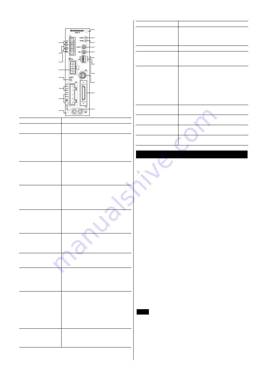
Names and functions of parts
POWER LED
ALARM LED
Current setting switch
Speed filter setting switch
Control mode selector
switch
Resolution switches
Pulse input mode
selector switch
Data edit connector
(CN4)
Motor connector (CN2)
Mounting hole
(at the back)
Mounting hole
(at the back)
CHARGE LED
I/O signals connector
(CN5)
Protective Earth Terminal
Electromagnetic brake
terminal (CN1)
Regeneration resistor
thermal input terminal (CN1)
24 VDC power supply
input terminal (CN1)
Regeneration resistor
terminal (CN3)
Power supply
input terminal (CN3)
Name Description
POWER LED (green)
This LED is lit while the main power or
24 VDC power is input.
ALARM LED (red)
This LED will blink when an alarm
generates (a protective function is
triggered). You can check the generated
alarm (triggered protective function) by
counting the number of times the LED
blinks.
CHARGE LED (red)
This LED will lit while the main power is
input. After the main power has been
turned off, the LED will turn off once the
residual voltage in the driver drops to a
safe level.
Current setting switch
(CURRENT)
This switch adjusts the operating current.
A desired current can be set as a
percentage (%) of the rated output
current.
(The factory setting is “F.”)
Speed filter setting
switch (V-FIL)
This switch adjusts the actuator
response. Adjust the switch if you want to
suppress actuator vibration or cause the
actuator to start/stop smoothly.
(The factory setting is “1.”)
Resolution switches
(D0/D1, CS0/CS1)
These two switches are used to toggle
the resolution per revolution of the motor
output shaft.
(The factory settings are “D0” and “CS0”).
Control mode selector
switch (NORM/CCM)
This switch toggles the driver between
the normal mode and current control
mode. (The factory setting is “NORM.”)
Pulse input mode
selector switch (2P/1P)
This switch is used to toggle between the
1-pulse input mode and 2-pulse input
mode according to the pulse output mode
of the controller.
(The factory setting is “2P.”)
24 VDC power supply
input terminal (CN1)
[24V]
Connects 24 VDC. Once a 24 VDC power
supply is connected, you can check the
contents of alarms that have generated
even when the main power is cut off. If an
actuator with an electromagnetic brake is
used, be sure to connect a 24 VDC power
supply as the electromagnetic brake
power.
Regeneration resistor
thermal input terminal
(CN1) [TH1, TH2]
Connects the regeneration unit
RGB100
.
If no regeneration unit is connected, plug
in the CN1 connector to short the TH1
and TH2 terminals.
Name Description
Electromagnetic brake
terminal (CN1) [MB1,
MB2]
Connects the lead wires of "cable for
electromagnetic brake" (24 VDC).
MB1: Electromagnetic brake
−
(black)
MB2: Electromagnetic brake + (white)
Motor connector (CN2)
Connects the actuator.
Regeneration resistor
terminal
(CN3) [RG1, RG2]
Connects the regeneration unit
RGB100
.
Power supply input
terminal (CN3)
•
Single-phase 100-115 V, single-phase
200-230 V
L, N: Connects a single-phase power
supply
•
Three-phase 200-230 V
L1, L2, L3: Connects a three-phase
power supply
•
NC: Not used.
Data edit connector
(CN4)
Connects a PC in which the
MEXE02
has
been installed, or the
OPX-2A
.
I/O signals connector
(CN5)
Connects the I/O signals.
Protective Earth
Terminal
Ground this terminal using a grounding
wire larger than AWG16 (1.25 mm
2
).
Mounting holes
(2 locations at the back)
These mounting holes are used to secure
the driver with screws.
Installation
Location for installation
The driver is designed and manufactured for installation in
equipment.
Install it in a well-ventilated location that provides easy access for
inspection. The location must also satisfy the following conditions:
•
Inside an enclosure that is installed indoors (provide vent holes)
•
Operating ambient temperature 0 to +50 °C (+32 to +122 °F)
(non-freezing)
•
Operating ambient humidity 85% or less (non-condensing)
•
Area that is free of explosive atmosphere or toxic gas (such as
sulfuric gas) or liquid
•
Area not exposed to direct sun
•
Area free of excessive amount of dust, iron particles or the like
•
Area not subject to splashing water (rain, water droplets), oil (oil
droplets) or other liquids
•
Area free of excessive salt
•
Area not subject to continuous vibration or excessive shocks
•
Area free of excessive electromagnetic noise (from welders,
power machinery, etc.)
•
Area free of radioactive materials, magnetic fields or vacuum
•
Up to 1000 m (3300 ft.) above sea level
Installation method
The driver is designed so that heat is dissipated via air convection
and conduction through the enclosure. Install the driver on a flat
metal plate [material: aluminium, 200×200×2 mm (7.87×7.87×0.08
in.) equivalent ] having excellent heat conductivity.
Note
•
Install the driver in an enclosure whose pollution
degree is 2 or better environment, or whose degree of
protection is IP54 minimum.
•
Do not install any equipment that generates a large
amount of heat or noise near the driver.
•
Do not install the driver underneath the controller or
other equipment vulnerable to heat.
•
Check ventilation if the ambient temperature of the
driver exceeds 50 °C (122 °F).
•
Be sure to install (position) the driver vertically.


