Connecting the Rear Power Cords and Data Cables
125
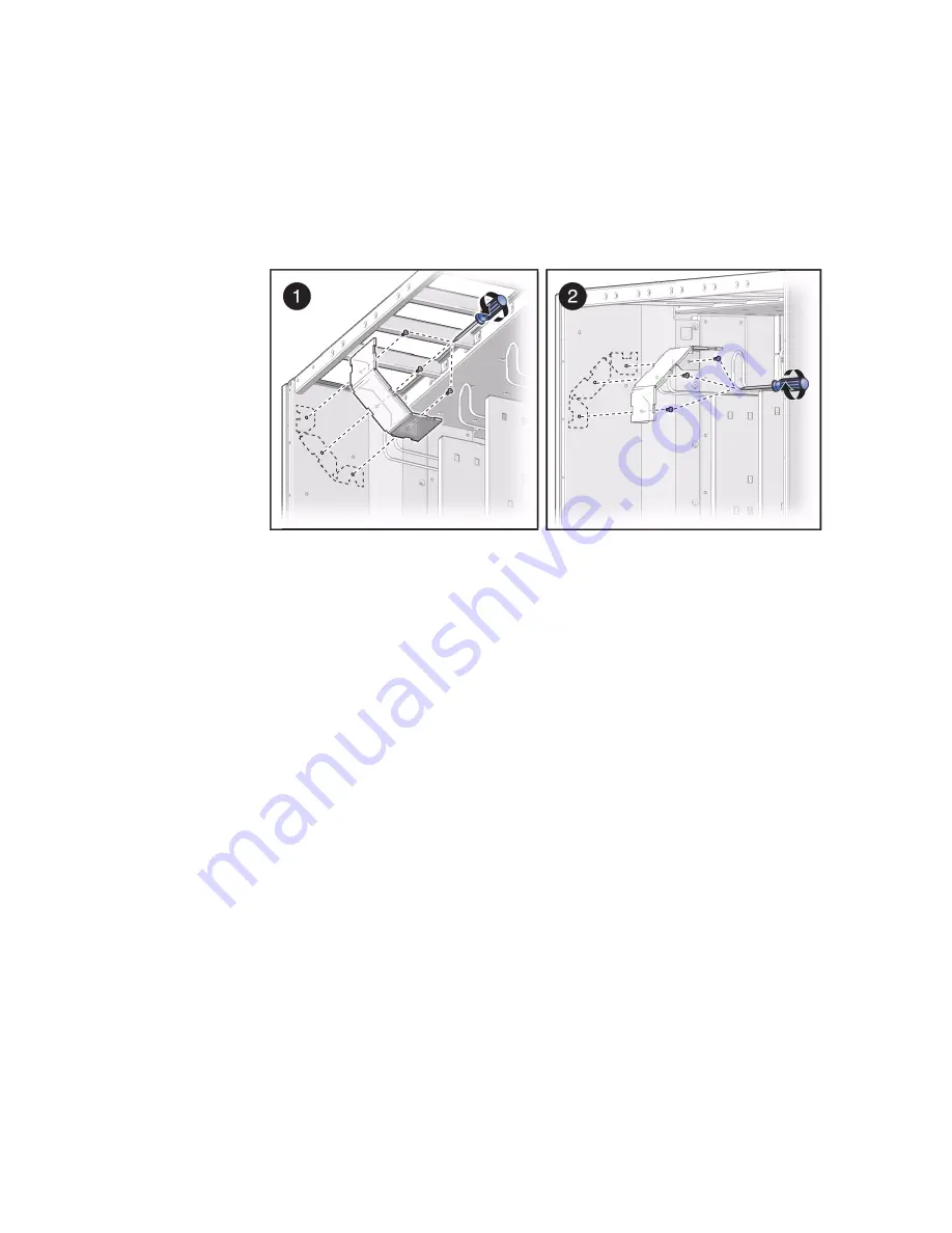
5. Use a T20 Torx screwdriver to remove the three M4X10 screws securing the left
cable bracket.
Remove and save the bracket and screws for the next steps.
6. Position the left cable bracket so that it faces downward in the left cable
channel.
7. Use a T20 Torx screwdriver to secure the left cable bracket to the left cable
channel with three M4X10 screws.
8. Continue with the installation by connecting the power cords.
See
“Connect the Power Cords” on page 126
.
Related Information
■
“Rear Cable Routing Options” on page 119
■
“Maximum Cable Connections” on page 121
■
“Cable Management Devices” on page 122
■
“Secure the Power Cords” on page 131
■
Summary of Contents for sparc M5-32
Page 1: ...SPARC M5 32 and SPARC M6 32 Servers Installation Guide Part No E41215 05 December 2014 ...
Page 8: ...viii SPARC M5 32 and SPARC M6 32 Servers Installation Guide December 2014 ...
Page 16: ...6 SPARC M5 32 and SPARC M6 32 Servers Installation Guide December 2014 Front Components ...
Page 18: ...8 SPARC M5 32 and SPARC M6 32 Servers Installation Guide December 2014 Rear Components ...
Page 21: ...Understanding the Server 11 FIGURE DCU Locations Rear of Server ...
Page 51: ...Preparing the Site 41 ...
Page 82: ...72 SPARC M5 32 and SPARC M6 32 Servers Installation Guide December 2014 ...
Page 106: ...96 SPARC M5 32 and SPARC M6 32 Servers Installation Guide December 2014 ...
Page 182: ...172 SPARC M5 32 and SPARC M6 32 Servers Installation Guide December 2014 ...


