-
36
-
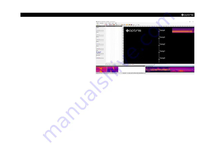
Figure 18: Layout BUGIS_Operation
Now start the layout BUGIS_Operation. The
shutters must be open for this step. To do
this, go to the Line scanner configuration via
Tools - Line scanner mode - Line scanner
settings
under the tab
General
click on the
Continuous
mode. After the fine adjustment
set the Line scanner configuration mode back
to
External triggered.
Now a few settings have to be made. The
scan line must be positioned correctly. The
scan line can be moved in the lower right
window (line scanner live view) in the
specified 5 points by clicking and dropping.
Alternatively, coordinates can also be entered via the line scan camera configuration via Line scanner
configuration.
Make absolutely sure that the width of the scan line is at least as wide as the glass passes through. This
ensures that the entire glass is scanned.
Summary of Contents for Bottom-Up GIS 450i G7
Page 1: ...Operators Manual Bottom Up GIS 640i G7 and 450i G7 Glass Inspection System ...
Page 11: ... Technical Data 11 Figure 1 Dimensions mm shutter system ...
Page 12: ... 12 Figure 2 Dimensions mm control cabinet ...
Page 13: ... Technical Data 13 Figure 3 Dimensions mm CTL 4M ...
Page 20: ... 20 CTL 4M FF optics Figure 5 spot size diagram ...
Page 27: ... Installation 27 Figure 10 camera distance ...
Page 44: ... 44 Figure 27 Linescan in PIX Connect software customized Layout ...
Page 52: ... 52 Appendix A Control cabinet Figure 34 Wiring diagram of control cabinet ...
Page 57: ...Bottom Up GIS MA E2022 04 A ...


