background image

OPTIMUM

M A S C H I N E N   -   G E R M A N Y

Operation

Version 1.0.1  dated 2015-05-27

Page 51

Original operating instructions

TU3008 | TU3008V

GB

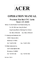
Polished section for recessing and cutting off

(for chip angle refer to table)

Img.4-30:

Polished section recessing and cutting off

Img.4-28:

Negative apex 
angle for rough-
ing

The ready-ground major cutting edge must be slightly ground with a grindstone for the plan-
ing.

For the roughing, a small chamfer must be produced with the grindstone in order to stabilize
the cutting edge against striking chips (b

f

 = f x 0.8).

Img.4-29:

Stabilize cutting 
edge

b

f

10°





Summary of Contents for OPTIturn TU 3008

Page 1: ...GB OPTIMUM M A S C H I N E N G E R M A N Y Operating manual Version 1 0 1 Item no 342 7200 Item no 342 7205 Lathe TU3008V...

Page 2: ...1 9 4 Protective cover lead screw and feed rod 14 1 10 Safety check 15 1 11 Personal protective equipment 15 1 12 Safety during operation 16 1 12 1 Disconnecting and securing the lathe 16 1 12 2 Usin...

Page 3: ...7 4 11 Tool holder 38 4 12 Lathe spindle fixture 38 4 12 1 Adjusting the Camlock bolts to the workpiece holder 40 4 12 2 Lathe chuck 40 4 12 3 Speed information maintenance recommendations reference s...

Page 4: ...asten Apron 85 6 7 Schlosskasten Apron 86 6 8 Planschlitten Cross slide 88 6 9 Oberschlitten Top slide 90 6 10 Maschinenbett Machine bed 92 6 11 Maschinenbett Machine bed TU3008V 93 6 12 Reitstock Tai...

Page 5: ...rvice life In the paragraph Maintenance all maintenance works and functional tests are described which the operator must perform in regular intervals The illustration and information included in the p...

Page 6: ...provisions for accident prevention the prohibition warning and mandatory signs as well as the warning notes on the lathe European standards must be observed during the installation operation maintena...

Page 7: ...ification of hazards We classify the safety warnings into different categories The table below gives an overview of the classification of symbols pictograms and the signal word for each specific dange...

Page 8: ...togram with or general danger with a warning of injury to hands hazardous electrical voltage rotating parts Warning danger of slip ping Warning risk of stumbling Warning hot surface Warning biological...

Page 9: ...l changes are not performed by the company Optimum Maschinen Germany GmbH It is also part of intended use that you observe the limits of the lathe the operating manual is observed the inspection and m...

Page 10: ...ed as intended When processing carbons graphite and carbon fibre rein forced carbons and similar materials the machine can be damaged quickly even if the dusts generated are completely sucked out duri...

Page 11: ...dangers involved in operating this machine We recommend visiting a training course in the operation of lathes Your specialist dealer can offer you an appropriate training course These courses are also...

Page 12: ...minium magnesium or using inflammable auxiliary materials e g spirit it is necessary to take additional preventive measures in order to safely avoid health risks 1 9 Safety devices Use the lathe only...

Page 13: ...the lathe chuck and the workpiece The emergency stop mushroom switch brings the machine to a standstill Turn the knob to the right to unlock the emergency stop mushroom switch CAUTION The emergency s...

Page 14: ...he is equipped with a lathe chuck protection The spindle of the lathe can only be switched on if the lathe chuck protection is closed Img 1 3 Lathe chuck shield 1 9 4 Protective cover lead screw and f...

Page 15: ...xceeds 80 dB A Before starting work make sure that the required personnel protective equipment is available at the work place CAUTION Dirty or contaminated personnel protective equipment can cause ill...

Page 16: ...tions have to be strictly observed dur ing assembly operation maintenance and repair Do not work on the lathe if your concentration is reduced for example because you are taking medication Stay at the...

Page 17: ...ing or after completing any mainte nance work this include covers safety instructions and warning signs grounding cables If you remove protection or safety devices refit them immediately after complet...

Page 18: ...ction 3x400V 50Hz 230V 50Hz 2 2 Power drive motor 1 1 KW 1 5 KW 2 3 Work areas Height of centres mm 180 Distance between centres mm 800 Swing diameter over machine bed mm 300 Swing diameter over cross...

Page 19: ...slide mm 65 Scale on the handwheel top slide 2mm per revolution Pitch 0 02mm Scale on the handwheel bed slide 5mm per revolution Pitch 0 5mm maximum dimension for lathe tool in Quadruplicate tool hold...

Page 20: ...OPTIMUM M A S C H I N E N G E R M A N Y Technical data Version 1 0 1 dated 2015 05 27 Page 20 Original operating instructions TU3008 TU3008V GB...

Page 21: ...he machine have been received 3 2 Scope of delivery When the lathe is delivered please check immediately that it has not been damaged during transport Also check that no fastening screws have come loo...

Page 22: ...ne base with lifting slings The lifting slings are fas tened within the machine bed Use two lifting slings for this purpose Img 3 1 Load suspension point 3 3 2 Lifting with lifting equipment Fasten th...

Page 23: ...0 1 dated 2015 05 27 Page 23 Original operating instructions TU3008 TU3008V GB 3 4 Machine Center of Gravity 3 4 1 without a machine base A A 0 1 A A 240 745 180 185 160 115 210 835 P 13 420 1420 410...

Page 24: ...nd the lathe according to the local safety regulations Work area on page 19 The work area for operation maintenance and repair must not be restricted INFORMATION In order to attain good functionality...

Page 25: ...l the moving parts and sliding surfaces are not damaged when the machine is operated Each unit leaves the factory with all its polished parts and sliding surfaces suitably greased to avoid oxi dation...

Page 26: ...ed by OPTIMUM as optional equipment Only use tool clamping devices in the intended admissible speed range 3 8 Electrical connection WARNING The three phase electrical connection of the TU3008 may only...

Page 27: ...lathe spindle are immediately operated at maximum load when cold this may result in damages INFORMATION For a long service life of your lathe during the first operating hours we recommend that you do...

Page 28: ...ive cover of the headstock 7 Change wheel and infeed table 8 Selector switch for feed direction 9 Selector switch for feed speed 10 Selector switch longitudinal feed with lead screw cross feed with fe...

Page 29: ...All failures should be eliminated immediately Stop the lathe immediately in the event of any abnormality in operation and make sure it cannot be started up accidentally or without authori sation Notif...

Page 30: ...R M A N Y Operation Version 1 0 1 dated 2015 05 27 Page 30 Original operating instructions TU3008 TU3008V GB 4 2 2 Overview of indicator elements Attachment screw lathe saddle Oil sight glass feed gea...

Page 31: ...ect turning direction Switch on spindle rotation Malfunctions on page 105 4 3 2 Switching on the TU8003V Switch on the main switch Check that the EMERGENCY STOP mushroom switch is not pressed or unloc...

Page 32: ...cuted using the emergency stop switch 4 5 Resetting an emergency stop condition Unlock the emergency stop switch again Set the rotation direction switch to the neutral central position Select turning...

Page 33: ...over Img 4 2 Protective cover of the headstock Img 4 3 Transmissions and V belt pulleys 4 7 2 Changing the speed or the speed range Loosen the nut on the tension pulley holder and unwind the V belt Li...

Page 34: ...on pulley and fasten the nut again The correct tension of the V belt is achieved when the V belt can be pressed down about 3mm with the forefinger ATTENTION Make sure that the tension pulley has conta...

Page 35: ...or levers Img 4 5 Changing the feed rate INFORMATION Use the table on the lathe for selecting the feed speed or the thread pitch Replace the change gears if the required thread pitch or feed cannot be...

Page 36: ...screws on the quadrant Img 4 8 Attachment of change gears Install the gear couples using the feed or change gear table and screw the gearwheels onto the quadrant again Swing the quadrant to the left...

Page 37: ...ding The tables are built up in a way that you may later on assemble the required combination to cut a thread without having to look up the details Ligature as orientation for the caming of one toothe...

Page 38: ...ol Use the tailstock with the centering point in order to determine the re quired height If necessary put the steel washers beneath the tool to achieve the required height Img 4 10 Height up to the tu...

Page 39: ...e chuck and the spindle fixture Fit lathe chuck Turn the clamp bolts 1 to the closed position CAUTION If the reference mark on the clamp bolt is not between the two V markings the chuck must be remove...

Page 40: ...ssive workpieces with higher degrees of stiffness lead to a considerable loss of clamping force This loss of clamping force is lower for thin walled distortion sensitive workpieces with less stiffness...

Page 41: ...espective drawing must be observed The workpieces must be clamped firmly and securely onto the lathe before they are machined The clamping force should be strong enough to ensure that the workpiece is...

Page 42: ...CAUTION The correct position of the clamping jaws is correct if after twisting together of the chuck jaws are centered at the center The clamping jaws and the three jaw chuck are equipped with numbers...

Page 43: ...r the jaws may break The following examples do not show all possible situa tions of danger Incorrect Correct Clamping length too long overhang too long Additional support over center or rest Clamping...

Page 44: ...ighten the locking screw and then the two front and rear adjusting screws Re tighten the adjusting screws of the tailstock ATTENTION Check clamping of the tailstock and the sleeve respectively for the...

Page 45: ...ligned to the limit stop The gauge must indicate the calculated value Vo Then the workpiece and the tool are clamped and positioned the bedslide is fixed The infeed is performed with the handwheel of...

Page 46: ...of the workpiece is per formed by a pulling pin and a lathe carrier The calculated value Vr is the offset measure of the tailstock The offset is monitored with the gauge also the return travel For th...

Page 47: ...ting speeds the following formula is to be applied Speed n 1 min Workpiece diameter d mm For lathes without continuously adjustable drive V belt drive speed gear the nearest speed is being selected De...

Page 48: ...St37 35 50 100 150 80 120 50 100 70 180 150 300 90 180 30 40 low alloy steel steel casting 42CrMo4 100Cr6 20 35 80 120 60 100 40 80 70 160 120 250 80 160 20 30 high alloyed steel steel casting X38CrMo...

Page 49: ...this might result in vibrations Img 4 20 Geometrically determined cut ter for the separa tion process Img 4 21 Cut and chip size Img 4 22 Cut A A posi tive cutter Img 4 23 Cut A A nega tive cutter We...

Page 50: ...l Clearance angle Chip angle Clearance angle Chip angle Steel 5 to 7 5 to 6 5 to 11 5 to 7 Cast iron 5 to 7 5 to 6 5 to 11 5 to 7 non ferrous metal 5 to 7 6 to 12 5 to 11 5 to 12 aluminium alloys 5 to...

Page 51: ...ngle refer to table Img 4 30 Polished section recessing and cutting off Img 4 28 Negative apex angle for rough ing The ready ground major cutting edge must be slightly ground with a grindstone for the...

Page 52: ...7 Tapping of external and internal threads Threads with smaller diameters and standard thread pitches should be tapped manually on the lathe with screw taps or dies by turning the clamping chuck as th...

Page 53: ...A Machine tools and general mechanical engineering UNJ UNJ 1 4 20UNJ Aircraft industry and aerospace industry Whitworth B S W W 1 4 in 20 B S W Cylindrical threads Pipe threads or conical pipe threads...

Page 54: ...0 838 0 693 0 729 0 153 0 135 0 036 0 75 M 1 1 0 25 0 938 0 793 0 829 0 153 0 135 0 036 0 85 M 1 2 0 25 1 038 0 893 0 929 0 153 0 135 0 036 0 95 M 1 4 0 3 1 205 1 032 1 075 0 184 0 162 0 043 1 1 M 1...

Page 55: ...56 639 56 639 3 681 3 248 0 866 58 Metric fine pitch thread Denomina tion of thread d x P Flank diameter d2 D2 Core diameter Denomina tion of thread d x P Flank diameter d2 D2 Core diameter Bolt Nut...

Page 56: ...e larger in their diameter as BSW Desig nation 1 8 28 BSP BSPT BSPT British Standard Pipe Taper Thread Conic tube thread cone 1 16 designation 1 4 19 BSPT BA BA British Association Standard Thread 47...

Page 57: ...ection towards the clamping chuck is selected and the machine spindle turns to the right the turning direction of the machine spindle is determined when you look into the spindle from the rear side If...

Page 58: ...o that the lathe will not coast too long Mount gear pairing for pitch 1 0 mm in the change gear Img 4 40 Pitch angle Pitch angle Pitch P Core diameter Flank diameter Thread diameter tan P D2 Abb 4 41...

Page 59: ...clamping chuck Immediately turn off the machine at the run out of the thread and cam the cutter out by turn ing the handwheel of the cross slide Turn the change over switch to the left Turn the machin...

Page 60: ...spindle must be secured by the operator using suitable covers A cover can be a sleeve that is mounted on the headstock that as a permanent safety device completely covers the protruding workpiece betw...

Page 61: ...Original operating instructions TU3008 TU3008V GB 4 20 Mounting of rests Follow and steady rests Use steady rest or follow rest to support longer parts and prevent the workpiece from flapping around...

Page 62: ...the rear of the tailstock By alternately loosening and tightening the two front and rear adjusting screws the tailstock is moved out of the central position The desired cross ad justment can be read o...

Page 63: ...48 Illustration Longitudinal turning 4 22 2 Face turning and recessing In the facing operation the tool feeds per pendicular to the axis of rotation of the workpiece Feed is done manually using the cr...

Page 64: ...be clamped in a way that it coincides exactly with the turning centre The threading engaging lever must be engaged during the whole thread cutting process This does not apply to thread pitches that c...

Page 65: ...fact when selecting your cool ing lubricant The company Optimum Maschinen Germany GmbH does not assume any guarantee for sub sequent damages due to unsuitable cooling lubricants The flashpoint of the...

Page 66: ...to personnel working on the lathe Damage to the lathe Only qualified personnel should carry out maintenance and repair work on the lathe Electrical systems and operating materials may only be install...

Page 67: ...ear depends to a large extent on the individual usage and operating conditions Any indicated intervals therefore are only valid for the corresponding approved con ditions Interval Where What How Start...

Page 68: ...k and reduces the play in the correspond ing guide Img 5 1 Take up screws slideways Start of work after every maintenance or repair work Feed gear Visual inspec tion Check the oil level in the inspect...

Page 69: ...ller hole Close the drain hole if no more oil drains Fill up to the middle of the reference mark of the oil sight glass into the filler hole using a suitable container Operating material Schmierstoffe...

Page 70: ...e Lathe saddle headstock Change gear Oiling Lubricate or fill all oilers with machine oil do not use a grease gun or similar equipment Use the oil bottle in the delivery volume Img 5 5 Oiler cup As re...

Page 71: ...riginal operating instructions TU3008 TU3008V GB As required Spindle bearing tighten If the initial tension of the tapered roller bearings decreases retighten it with the adjusting nut Img 5 7 Re lubr...

Page 72: ...lubricant should be of high quality and provided for high pres sure bearing surfaces The lubricant should withstand the coolant and other chemicals Numerous different lathe chucks are available on th...

Page 73: ...TU3008V GB Optimum Maschinen Germany GmbH accepts no liability nor does it guarantee against damage and operating malfunctions resulting from failure to observe these operating instructions For repair...

Page 74: ...OPTIMUM M A S C H I N E N G E R M A N Y Maintenance Version 1 0 1 dated 2015 05 27 Page 74 Original operating instructions TU3008 TU3008V GB...

Page 75: ...XP 150 SPARTAN EP 150 Kl beroil GEM 1 150 Mobilgear 629 Shell Omala 150 Meropa 150 VG 100 CLP 100 Aral Degol BG 100 BP Energol GR XP 100 SPARTAN EP 100 Kl beroil GEM 1 100 Mobilgear 627 Shell Omala 1...

Page 76: ...OPTIMUM M A S C H I N E N G E R M A N Y 1 0 1 2015 05 27 76...

Page 77: ...A N Y Ersatzteile Spare parts Version 1 0 1 2015 05 27 77 Originalbetriebsanleitung TU3008 TU3008V DE GB 6 Ersatzteile Spare parts 6 1 Spindelstock Headstock Abb 6 1 Spindelstock Headstock 11 10 9 8...

Page 78: ...satzteile Spare parts Version 1 0 1 2015 05 27 78 Originalbetriebsanleitung TU3008 TU3008V DE GB 6 2 Spindelstock Headstock Abb 6 2 Spindelstock Headstock 38 51 66 44 12 13 35 34 14 17 16 16 15 18 19...

Page 79: ...ter Eccentric 1 03427205 1 13 14 Welle Shaft 1 03427205 1 14 15 Spannrolle Pressure roll 1 03427205 1 15 16 Kugellager Bearing 4 6001 0406001 2R 17 Sicherungsring Retaining ring 3 28 18 Sicherungsring...

Page 80: ...1 03427205 2 01 2 Klemmmutter Clamping nut 2 03427205 2 02 3 Bolzen Bolt 2 03427205 2 03 4 H lse Sleeve 2 03427205 2 04 5 Scheibe Washer 2 03427205 2 05 6 Scheibe Washer 1 03427205 2 06 7 Platte Plat...

Page 81: ...1 2015 05 27 81 Originalbetriebsanleitung TU3008 TU3008V DE GB 6 4 Vorschubgetriebe Feed gear Abb 6 4 Vorschubgetriebe Feed gear 1 64 28 41 60 60 39 39 29 68 30 42 71 71 42 68 30 29 68 71 42 30 31 35...

Page 82: ...05 27 82 Originalbetriebsanleitung TU3008 TU3008V DE GB 6 5 Vorschubgetriebe Feed gear Abb 6 5 Vorschubgetriebe Feed gear 27 26 6 26 25 1 40 17 16 11 21 24 14 24 23 20 73 22 15 17 19 40 70 66 3 5 9 8...

Page 83: ...atte Plate 3 03427205 3 30 31 Bolzen Bolt 1 03427205 3 31 32 Kupplung Clutch 1 03427205 3 32 33 Hebel Lever 1 03427205 3 33 34 Wahlschalter Selector switch 1 03427205 3 34 35 Zeiger Indicator 3 034272...

Page 84: ...ersion 1 0 1 2015 05 27 84 Originalbetriebsanleitung TU3008 TU3008V DE GB 72 Dichting Seal 1 03427205 3 72 73 Sicherungsring Retaining ring 1 15 Teileliste Vorschubgetriebe Parts list feed gear Pos Be...

Page 85: ...arts Version 1 0 1 2015 05 27 85 Originalbetriebsanleitung TU3008 TU3008V DE GB 6 6 Schlosskasten Apron Abb 6 6 Schlosskasten Apron 36 29 49 8 7 48 44 6 63 5 61 18 52 54 19 32 51 16 17 15 20 47 3 4 30...

Page 86: ...Ersatzteile Spare parts Version 1 0 1 2015 05 27 86 Originalbetriebsanleitung TU3008 TU3008V DE GB 6 7 Schlosskasten Apron Abb 6 7 Schlosskasten Apron 57 35 68 38 33 64 24 64 23 1 39 9 13 12 11 14 10...

Page 87: ...1 03427205 4 32 33 Exzenter Eccentric 1 03427205 4 33 34 Nabe Collet 1 03427205 4 34 35 Platte Plate 1 03427205 4 35 36 H lse Sleeve 1 03427205 4 36 37 Gewindestift Grub screw 1 03427205 4 37 38 Zyli...

Page 88: ...ts Version 1 0 1 2015 05 27 88 Originalbetriebsanleitung TU3008 TU3008V DE GB 6 8 Planschlitten Cross slide Abb 6 8 Planschlitten Cross slide 35 36 27 28 23 26 66 22 23 54 21 24 25 25 17 20 66 60 52 6...

Page 89: ...427205 6 27 28 Schraube Screw 1 M5x8 35 H lse Sleeve 1 03427205 6 35 37 Platte Plate 1 03427205 6 37 38 Platte Plate 1 03427205 6 38 39 Platte Plate 1 03427205 6 39 40 Platte Pa 1 03427205 6 40 41 Abs...

Page 90: ...rsatzteile Spare parts Version 1 0 1 2015 05 27 90 Originalbetriebsanleitung TU3008 TU3008V DE GB 6 9 Oberschlitten Top slide Abb 6 9 Oberschlitten Top slide 57 5 3 4 6 2 71 67 68 62 61 16 8 7 13 15 5...

Page 91: ...3427205 7 13 14 Skalenring Scala ring 1 03427205 7 14 15 F hrung Giuide 1 03427205 7 15 16 Spindelmutter Spindle nut 1 03427205 7 16 36 Schraube Screw 1 03427205 7 36 50 Innensechskantschraube Socket...

Page 92: ...rsatzteile Spare parts Version 1 0 1 2015 05 27 92 Originalbetriebsanleitung TU3008 TU3008V DE GB 6 10 Maschinenbett Machine bed Abb 6 10 Maschinenbett Machine bed 1 25 26 14 14 13 43 3 15 2 4 34 28 2...

Page 93: ...tzteile Spare parts Version 1 0 1 2015 05 27 93 Originalbetriebsanleitung TU3008 TU3008V DE GB 6 11 Maschinenbett Machine bed TU3008V Abb 6 11 TU3008V Maschinenbett Machine bed 10 6 18 8 9 7 37 22 23...

Page 94: ...1 03427205 8 20 21 Abdeckung Cover 1 03427205 8 21 22 Winkel Angle 1 03427205 8 22 23 Gabel Sicherheitsschalter Fork Safety switch 1 03427205 8 23 24 Sicherheitsschalter Safety switch 1 03427205 8 24...

Page 95: ...Ersatzteile Spare parts Version 1 0 1 2015 05 27 95 Originalbetriebsanleitung TU3008 TU3008V DE GB 6 12 Reitstock Tailstock Abb 6 12 Reitstock Tailstock 29 5 6 19 9 22 2 19 8 20 7 15 24 14 16 17 18 12...

Page 96: ...1 51200 04051200 12 Hebel Lever 1 03427205 9 12 13 Sechskantschraube Hexagon screw 1 M8x80 14 Handrad Handle 1 03427205 9 14 15 Skalenring Scale ring 1 03427205 9 15 16 Scheibe Washer 1 8 17 Sechskan...

Page 97: ...sion 1 0 1 2015 05 27 97 Originalbetriebsanleitung TU3008 TU3008V DE GB 6 13 Mitlaufende L nette Follow rest Abb 6 13 Mitlaufende L nette Follow rest 6 14 Feststehende L nette Steady rest Abb 6 14 Fes...

Page 98: ...6 Einstellschraube Ajust screw 2 03427205 20 06 7 Scheibe Washer 2 DIN 125 A 8 4 8 Innensechskantschraube Socket head screw 2 ISO 4762 M8 x 30 Teileliste feststehende L nette Parts list steady rest P...

Page 99: ...rtikelnummer Qty Size Item no 1 Halter Holder 1 03427205 30 01 2 Welle Shaft 1 03427205 30 02 3 Schalter Switch 1 03427205 30 03 4 Drehfutterschutz Lathe chuck cover 1 03427205 30 04 5 Sichtschutzglas...

Page 100: ...rtikelnummer Qty Size Item no 1 Halter Holder 1 03427205 40 01 2 Stange Rod 1 03427205 40 02 3 Aufnahme Collet 1 03427205 40 03 4 Abdeckung Cover 1 03427205 40 04 5 Klemmplatte Clamping plate 1 034272...

Page 101: ...M M A S C H I N E N G E R M A N Y Ersatzteile Spare parts Version 1 0 1 2015 05 27 101 Originalbetriebsanleitung TU3008 TU3008V DE GB 6 17 Schaltplan Wiring diagram TU3008 Abb 6 17 Schaltplan Wiring d...

Page 102: ...nge Gr sse Artikelnummer Qty Size Item no 1B2 1 Schalter Riemenabdeckung Belt cover switch 1 03427200B1 1B2 2 Schalter Drehfutterschutz Lathe chuck switch 1 03427200B2 1K4 Motorrelais Motor relay 1 03...

Page 103: ...M A S C H I N E N G E R M A N Y Ersatzteile Spare parts Version 1 0 1 2015 05 27 103 Originalbetriebsanleitung TU3008 TU3008V DE GB 6 18 Schaltplan Wiring diagram TU3008V Abb 6 18 Schaltplan Wiring d...

Page 104: ...eed indicator 1 034272051A7 1B7 Drehzahlsensor Rotation speed sensor 1 034272051B7 1G7 Netzteil Power pack 1 034272051G7 1R7 Potentiometer Potentiometer 1 034272051R7 M1 Antriebsmotor Drive motor 1 03...

Page 105: ...adius V belt squeaks V belt slips V belt wear down V belt tension is too loose V belt check re tighten on page 69 Speed of rotation varies too much Workpiece becomes conical Centre are not aligned tai...

Page 106: ...threaded is wrong Lathe tool is clamped incorrectly or grinding has been started the wrong way Wrong pitch Wrong diameter Set the lathe tool to the centre grind angle correctly Use 60 lathe tool for m...

Page 107: ...the lead screw Lead screw Threaded shaft for tapping threads Feed rod Shaft without threads for transferring the feed to the saddle or cross slide Lathe chuck Clamping tool for holding the workpiece...

Page 108: ...iability and warranty claims Using the product beyond the technical options and proper use in particular due to over straining of the machine Any defects arising by one s own fault due to faulty opera...

Page 109: ...your municipal waste manage ment If appropriate call on the help of a specialist waste disposal company for the treatment of the material Please make sure that the electrical components are disposed...

Page 110: ...lable and gener ally need to be supplied to the material reuse The packaging wood can be supplied to the disposal or the reuse Any packaging components made of cardboard box can be chopped up and supp...

Page 111: ...osal constitutes a risk to the environment and public health Recycling of material will help reduce the consumption of raw materials For further information about the recycling of this product please...

Page 112: ...he safety objective meet the requirement of EC Directive 2006 95 EC The following harmonized standards were applied EN 1037 1995 A1 2008 Safety of machinery Prevention of unexpected start up EN ISO 14...

Page 113: ...nt of EC Directive 2006 95 EC The following harmonized standards were applied EN 1037 1995 A1 2008 Safety of machinery Prevention of unexpected start up EN ISO 14119 Safety of machinery Interlocking d...

Page 114: ...and recessing 63 First commissioning 26 I Inch thread 56 Indexable inserts 57 Indicator elements 30 Inspection 66 L Lathe chuck protection 14 Load end position 22 Longitudinal turning 63 Lubrication...

Reviews: