background image

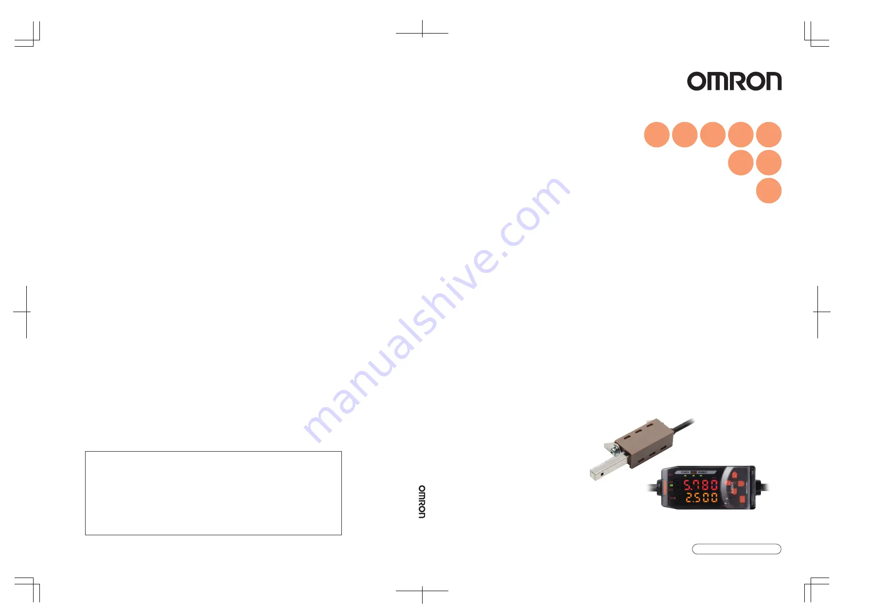
Smart Electrostatic Sensor

ZJ-SD Series

User's Manual

Cat. No. Z237-E1-02

ZJ-SD Series Smart Electrostatic Sensor  

User's Man

ual

Cat.

 No.

 Z237-E1-02

©

OMRON Corporation 2005

        All Rights Reserved.

Note: Specifications subject to change without notice.

Printed in Japan.

1106-0.1M (1205) (M)

Authorized Distributor:

Cat. No. Z237-E1-02

OMRON Corporation
Industrial Automation Company

Sensing Devices Division H.Q.
Application Sensors Division

Shiokoji Horikawa, Shimogyo-ku,
Kyoto, 600-8530 Japan
Tel: (81)75-344-7068/Fax: (81)75-344-7107

Regional Headquarters

OMRON EUROPE B.V.

Sensor Business Unit,
Carl-Benz-Str. 4, D-71154 Nufringen,
Germany
Tel: (49)7032-811-0/Fax: (49)7032-811-199

OMRON ELECTRONICS LLC

1 East Commerce Drive, Schaumburg, IL 60173
U.S.A.
Tel: (1)847-843-7900/Fax: (1)847-843-8568

OMRON ASIA PACIFIC PTE. LTD.

83 Clemenceau Avenue, 
#11-01, UE Square,
239920 Singapore
Tel: (65)6835-3011/Fax: (65)6835-2711

OMRON (CHINA) CO., LTD. 

Room 2211, Bank of China Tower, 
200 Yin Cheng Road (M), 
Shanghai, 200120 China
Tel: (86)21-5037-2222/Fax: (86)21-5037-2200

Summary of Contents for ZJ-SD Series

Page 1: ...on Sensors Division Shiokoji Horikawa Shimogyo ku Kyoto 600 8530 Japan Tel 81 75 344 7068 Fax 81 75 344 7107 Regional Headquarters OMRON EUROPE B V Sensor Business Unit Carl Benz Str 4 D 71154 Nufringen Germany Tel 49 7032 811 0 Fax 49 7032 811 199 OMRON ELECTRONICS LLC 1 East Commerce Drive Schaumburg IL 60173 U S A Tel 1 847 843 7900 Fax 1 847 843 8568 OMRON ASIA PACIFIC PTE LTD 83 Clemenceau Av...

Page 2: ...uired for using the ZJ SD When using the ZJ SD be sure to observe the following The ZJ SD must be operated by personnel knowledgeable in electrical engineering To ensure correct use please read this manual thoroughly to deepen your understanding of the product Please keep this manual in a safe place so that it can be referred to whenever necessary ...

Page 3: ...ection 4 Section 5 Section 6 Section 7 APPLICATION CONSIDERATIONS Please Read FEATURES PREPARATION FOR MEASUREMENT BASIC OPERATION MAIN APPLICATIONS AND SETTING METHODS DETAILED SETTINGS AUXILIARY FUNCTIONS APPENDICES User s Manual Smart Electrostatic Sensor ZJ SD Series operation2 book Page 1 Wednesday November 29 2006 2 56 PM ...

Page 4: ...E PRODUCTS WILL SUITABLY MEET THE REQUIREMENTS OF THEIR INTENDED USE OMRON DISCLAIMS ALL OTHER WARRANTIES EXPRESS OR IMPLIED LIMITATIONS OF LIABILITY OMRON SHALL NOT BE RESPONSIBLE FOR SPECIAL INDIRECT OR CONSEQUENTIAL DAMAGES LOSS OF PROFITS OR COMMERCIAL LOSS IN ANY WAY CONNECTED WITH THE PRODUCTS WHETHER SUCH CLAIM IS BASED ON CONTRACT WARRANTY NEGLIGENCE OR STRICT LIABILITY In no event shall r...

Page 5: ...equipment amusement machines vehicles safety equipment and installations subject to separate industry or government regulations Systems machines and equipment that could present a risk to life or property Please know and observe all prohibitions of use applicable to the products NEVER USE THE PRODUCTS FOR AN APPLICATION INVOLVING SERIOUS RISK TO LIFE OR PROPERTY WITHOUT ENSURING THAT THE SYSTEM AS...

Page 6: ...ons PROGRAMMABLE PRODUCTS OMRON shall not be responsible for the user s programming of a programmable product or any consequence thereof COPYRIGHT AND COPY PERMISSION This document shall not be copied for sales or promotions without permission This document is protected by copyright and is intended solely for use in conjunction with the product Please notify us before copying or reproducing this d...

Page 7: ...ed Connect a supply voltage and current within the rated ranges to the output terminals Others Do not disassemble repair or modify this product This product is not compatible with the ZX series Do not connect a ZJ S___ in combination with a ZX series Amplifier Unit Supply power from a UL Class 2 DC power supply or a DC power supply unit that has a countermeasure safety ultra low voltage circuit bu...

Page 8: ... cable ZX XC_A must be used For extension of the cable of Amplifier Units shielded cables of the same type must be used When using a commercially available switching regulator make sure that the FG Frame Ground terminal is grounded If surge currents are present in the power lines connect surge absorbers that suit the operating environment When two or more Amplifier Units are connected by a Calcula...

Page 9: ...period from the start to the end of hold measurements is called the sampling period The value to be held during that sampling period is selected here Setting the Trigger for Measurement in the Hold Mode Set the Trigger Direction and Self trigger Level Setting the Delay Time Set the mode switch to FUN Use the LEFT and RIGHT keys to display HOLD on the main display Use the UP and DOWN keys to select...

Page 10: ...n procedure Operation steps are numbered to indicate their order Visual Aids Indicates points that are important to achieve the full product performance such as operational precautions and application procedures Indicates pages where related information can be found Indicates information helpful in operation operation2 book Page viii Wednesday November 29 2006 2 56 PM ...

Page 11: ...ote vii CONTENTS ix Section 1 FEATURES 1 ZJ SD Features 2 Section 2 PREPARATION FOR MEASUREMENT 5 Basic Configuration 6 Part Names and Functions 9 Installing the Amplifier Unit 13 Installing Sensor Heads 15 Mounting on the Mounting Bracket 17 Connections 19 Wiring Input Output Cables 23 operation2 book Page ix Wednesday November 29 2006 2 56 PM ...

Page 12: ...Setting the Installation Distance 41 Section 4 MAIN APPLICATIONS AND SETTING METHODS 45 Measuring Sheet Workpieces 46 Section 5 DETAILED SETTINGS 51 Setting the Number of Samples to Average 52 Using the Hold Functions 53 Entering Threshold Values 64 Linear Output 70 Setting Judgment Output Timing Timer 79 Setting the Warning Level Output type 82 Using the Area Correction Function 85 Selecting Bank...

Page 13: ...ta 97 Changing Display Scales 99 Comparing Measured Values Differentiation Function 105 Section 7 APPENDICES 109 Troubleshooting 110 Error Messages and Countermeasures 111 Q A 113 Glossary 114 Specifications and Dimensions 115 Communicating with the Static Electricity Smart Monitor via the Interface Unit 124 Characteristic Data 126 Quick Reference for Displays 127 INDEX 131 Revision History 136 op...

Page 14: ...xii Introduction CONTENTS ZJ SD User s Manual Introduction CONTENTS MEMO operation2 book Page xii Wednesday November 29 2006 2 56 PM ...

Page 15: ...Section 1 FEATURES 1 ZJ SD User s Manual S e c t i o n 1 FEATURES ZJ SD Features 2 operation2 book Page 1 Wednesday November 29 2006 2 56 PM ...

Page 16: ... the workpiece is greatly dependent on the distance up to the workpiece The ZJ SD series can be connected to a ZX displacement sensor so that distance correction can be performed on the charged amount using that measurement data and non uniform workpieces can be measured to high precision Also if the installation distance up to the workpiece is fixed beforehand distance correction can be performed...

Page 17: ...us on a Personal Computer Use an Interface Unit and Static Electricity Smart Monitor to view measurement waveforms and log measurement data on a personal computer This function is useful for making on site measurement adjustments and for day to day quality control p 12 p 124 Special extension cable Static Electricity Smart Monitor Amplifier Unit Interface Unit operation2 book Page 3 Wednesday Nove...

Page 18: ...4 Section 1 FEATURES ZJ SD User s Manual Section 1 ZJ SD Features MEMO operation2 book Page 4 Wednesday November 29 2006 2 56 PM ...

Page 19: ... PREPARATION FOR MEASUREMENT Basic Configuration 6 Part Names and Functions 9 Installing the Amplifier Unit 13 Installing Sensor Heads 15 Mounting on the Mounting Bracket 17 Connections 19 Wiring Input Output Cables 23 operation2 book Page 5 Wednesday November 29 2006 2 56 PM ...

Page 20: ...g cable Sensor Head Extension Cable Calculating Unit Amplifier Unit Power Supply p 22 p 13 p 15 p 20 Enables operation of Amplifier Units from the personal computer and monitoring measured values Used to connect to a personal computer or programmable controller ZJ SD100 Detects static electricity Basic Configuration ZJ SDA11 Performs measurements and outputs measurement results DC24V 10 ZX XC1A 1 ...

Page 21: ...asic configuration Example 1 Example 2 1ch ultrasonic sensor 2ch static electricity sensor The static electricity sensor on 2ch can perform correction using the data of the ultrasonic sensor on 1ch 1ch ultrasonic sensor 2ch static electricity sensor The static electricity sensor on 2ch to 5ch can perform correction using the data of the ultrasonic sensor on 1ch 3ch static electricity sensor 4ch st...

Page 22: ...ng the data of the ultrasonic sensor on 1ch 1ch ultrasonic sensor 2ch static electricity sensor 3ch static electricity sensor 4ch static electricity sensor 0ch Interface Unit When Reference destination setting is set to Next CH the static electricity sensor on 2ch and 4ch can perform correction using the data of the ultrasonic sensors on 1ch and 3ch respectively 4ch cannot reference 1ch and 2ch ca...

Page 23: ... result or warning state p 10 9 The OPE2 indicator lights according to the judgment result or warning state p 10 10 The OPE3 indicator lights according to the judgment result or warning state p 10 11 The main display shows measured values and function names 12 The sub display shows additional information and function setting values for measurements Reading Displays p 29 13 The threshold switch sel...

Page 24: ...e Peak OK ON when the peak hold result is OK PASS Bottm OK ON when the bottom hold result is OK PASS The warning state continues until one of Reset input ON Switch to FUN mode and Power OFF is executed Hold Output type OPE1 OPE2 OPE3 Other than peak and bottom hold Standard HIGH PASS LOW Warning WARN OK NG Peak and bottom hold Warning standard WARN Peak OK Bottm OK operation2 book Page 10 Wednesda...

Page 25: ...d Sensor Head Calculating Unit Sensing section Connector Connect to the Amplifier Unit Preamplifier Display Display Connector two connectors one on each side Connection indicator Lit when the Amplifier Unit is connected Connect to the Amplifier Unit operation2 book Page 11 Wednesday November 29 2006 2 56 PM ...

Page 26: ...plied 4 BUSY Lights during communications with the Smart Sensor ERR Lights if an error occurs during communications with the Smart Sensor 5 BUSY Lights during communications with the personal computer ERR Lights if an error occurs during communications with the personal computer Display 2 Amplifier Unit connector 1 Connector Display 3 Power supply indicator 5 External terminal communication indica...

Page 27: ... of the Amplifier Unit on the DIN Track and press in at the bottom until the Unit locks into place Always hook the connector end of the Amplifier Unit on the DIN Track first The mounting strength may decrease if the output cable end is hooked on the DIN Track first DIN Track Option PFP 100N 1 m PFP 50N 0 5 m PFP 100N2 1 m End Plate option PFP M Hook on the connector end operation2 book Page 13 Wed...

Page 28: ...Unit Removal Method Push the Amplifier Unit up and pull out from the connector end Using the Product in Conformance with CE To use this product in conformance with CE install the enclosed ferrite core as shown below 10 mm max Ferrite core operation2 book Page 14 Wednesday November 29 2006 2 56 PM ...

Page 29: ...end using the exclusive mounting bracket ZJ XBU1 Do not allow anything to touch the metal case of the Sensor Head Failure to do so might prevent accurate measurement by the sensor Setting the Installation Distance p 41 Scaling p 99 2 Adjust the angle of the Sensor Head Loosen the two screws on the sides of the holder and adjust the angle of the Sensor Head so that it faces the object to be measure...

Page 30: ...to the bracket 3 Fit the other end of the Preamplifier into the bracket To remove the Preamplifier from the mounting bracket lift upwards while holding the center of the Preamplifier Using the Product in Conformance with CE To use this product in conformance with CE loop the cable twice around the enclosed ferrite core as shown below Fit one end into the bracket Fit the other end into the bracket ...

Page 31: ...mple of mounting the ZX LD___ 1 Fix the ZX LD___ onto the mounting bracket ZJ XBU1 using M3 screws The screws must be tightened with a torque of 0 3 Nm or less Take care not to touch the emitting receiving section of the Sensor Head Adhesion of finger marks may prevent correct measurements If you have touched them wipe them with a clean soft cloth 2 Fix the ZJ S___ using the screws Do not allow an...

Page 32: ...ut must be tightened with a torque of 45 Nm or less 2 Fix the ZJ S___ using the screws Do not allow anything to touch the metal case of the Sensor Head Failure to do so might prevent accurate measurement by the sensor Tighten by holding the M18 tightening nut supplied between your fingers to secure Wave emitting receiving section 18 5 mm dia 0 5 0 Sensing section operation2 book Page 18 Wednesday ...

Page 33: ...ector Connecting the Sensor Head Push the Sensor Head connector into the Amplifier Unit connector until it locks Disconnecting the Sensor Head To disconnect the Sensor Head hold the Sensor Head s connector ring and the Amplifier Unit connector and then pull them straight out Be sure to hold the connector of the Amplifier Unit to disconnect it Failure to do so may damage the input cable of the Ampl...

Page 34: ... Amplifier Units Connection Method 1 Open the connector cover on the Amplifier Unit Open the connector cover by lifting and sliding it open 2 Mount the Calculating Unit onto the DIN Track 3 Slide and connect the Calculating Unit to the Amplifier Unit connector 4 Slide and connect the second Amplifier Unit to the Calculating Unit connector To disconnect the Calculating Unit perform the above operat...

Page 35: ...FOR MEASUREMENT Section 2 Connections Channel Numbers of Amplifier Units The following diagram shows the channel numbers when two or more Amplifier Units are connected CH1 CH2 CH3 CH4 CH5 operation2 book Page 21 Wednesday November 29 2006 2 56 PM ...

Page 36: ...it open 2 Mount the Interface Unit onto the DIN Track 3 Slide and connect the Interface Unit to the Amplifier Unit connector To disconnect the Interface Unit perform the above operations in reverse order When two or more Amplifier Units are used connect the Interface Unit to the Amplifier Unit with the highest channel number Communication with the static electricity Smart Monitor is possible via t...

Page 37: ... from the other ground wires Always ground the linear output terminal even when linear output is not used When using Calculating Units make sure that the linear GND lines of the Amplifier Units are connected to each other 8 When this input is ON The bank is switched using 9 10 and 11 p 88 9 8 ON Bank switching is executed p 88 8 OFF The zero reset input is used to execute and clear zero reset p 37...

Page 38: ... 24 VDC GND 0V 24 VDC Linear output Linear GND Reset input Timing input Zero reset input Bank shift input OPE3 judgment output OPE2 judgment output OPE1 judgment output Voltage output 4V Current output 4 to 20 mA Current voltage output Switch Voltage output 10 kΩ or higher Current output 300 Ω or lower Load Load Load Internal circuit operation2 book Page 24 Wednesday November 29 2006 2 56 PM ...

Page 39: ... OPERATION Flow of Operation 26 Basic Knowledge for Operation 28 Function Transition Charts 33 Correcting the Measurement Reference Voltage 36 Selecting the Measurement Mode 40 Setting the Installation Distance 41 operation2 book Page 25 Wednesday November 29 2006 2 56 PM ...

Page 40: ...on Function Setting Judgment Conditions Entering Threshold Values Linear Output Setting Judgment Output Timing Preparation for Measurement Setting to Execution of Measurement Conditions Installation and Connection Preparation for Measurement Select the measurement mode standard high precision p 40 Changing Display Scales Setting Output Contents p 85 Selecting the Measurement Mode Setting the Dista...

Page 41: ...of Terms Glossary Want to Find Contents from Digital Displays Quick Reference for Displays Saving the Zero Reset Level for the Reference Voltage in Zero Reset Memory Changing the Number of Display Digits Using the Power Saving Mode Reversing the Display during a Zero Reset Key Lock Function Initializing Setting Data Applied Use of Functions Additional Functions Changing Deleting Settings Setting t...

Page 42: ...ee modes Use the Mode Switch on the Amplifier Unit to switch between modes Switch to the desired mode before starting operation Function Transition Charts p 33 Mode Description RUN Normal operation mode T Mode for setting the threshold values FUN Mode for setting measurement conditions POWER kV operation2 book Page 28 Wednesday November 29 2006 2 56 PM ...

Page 43: ...ted For example when the hold function is set the held value is displayed Displays the threshold value voltage current resolution distance and present value in order when the Control Keys are pressed Threshold Value Display Displays either the HIGH or LOW threshold value depending on the position of the threshold switch T Displays the measured value the value after the measurement conditions have ...

Page 44: ...ges the sub display content Used when selecting the numeric value digit The function changes depending on the setting Switches the function display Selects the numeric value digit Stops setting UP Key Performs timing input Used when changing numeric values The function changes depending on the setting Switches between selections Changes numeric values DOWN Key Resets input ENT Key When held down f...

Page 45: ...a peak hold as the hold condition Moving to FUN mode and HOLD 1 Set the mode switch to FUN 2 Use the LEFT and RIGHT keys to display HOLD on the main display Setting Hold Conditions 3 Press the UP or DOWN key The sub display flashes 4 Use the UP and DOWN keys to select P H Press either the LEFT or RIGHT key to cancel the selected option The display returns to the current setting OFF in this example...

Page 46: ... on the sub display 3 Press any cursor key The first digit on the sub display flashes to indicate that direct input is enabled 4 Use the UP and DOWN keys to display 3 5 Use the LEFT or RIGHT key to move the cursor to the one s digit 6 Use the UP and DOWN keys to display 9 To cancel the selected setting use the LEFT key to move the cursor to the leftmost digit and press the LEFT key again Alternati...

Page 47: ...e setting shown in the above diagram is only an example The actual display may be different In the RUN and T modes the position of the threshold switch determines whether the HIGH or LOW threshold is displayed Main Display Sub display 1 When the mode is switched to RUN the measured and threshold values are displayed first Threshold 1 Linear output voltage value Measured value 1 The main display al...

Page 48: ...iation function Linear output correction Monitor focus Differentiation cycle ECO Mode Display reverse Warning level Output type Zero reset memory settings Non measurement settings Clamp value setting All the special functions are displayed if is selected Bank switching p 107 Display digit limit 2 Displayed if the hold function is not set to OFF Sensor distance value Trigger Self trigger level High...

Page 49: ...hold Delay time Sampling period Timer Timer time Special Initialization This symbol requests you to move to another menu using the LEFT or RIGHT key after pressing the ENT key to confirm the selections Area measurement Hold p 53 p 79 p 85 Area correction p 86 operation2 book Page 35 Wednesday November 29 2006 2 56 PM ...

Page 50: ...ecause the plate is not grounded properly The same measurement results can be obtained with a jig or other object as long as the conditions given for the reference detection object are met Linearity Reference Values The linearity shown in the following graph can be obtained by resetting zero as described above A B Material Conductive metal plate Dimension A 5L1 Dimension B 5L1 Thickness t 1 mm Con...

Page 51: ... the Reference Voltage in Zero Reset Memory p 38 1 Place the reference sensing object in position 2 Set the mode switch to RUN 3 Press the ENT key at least one second or input the zero reset signal from an external device for 800 ms max This registers the reference value and the zero reset indicator lights The tolerance for the registered reference value is displayed on the main display Clearing t...

Page 52: ...t every time zero is reset The write life of the EEPROM is 100 000 writes If the zero reset level is written every time measurements are taken malfunction may occur Manage the write life when turning ON zero reset memory during operation Even if the zero reset memory is turned OFF the zero reset level will be saved whenever threshold values or other function settings are changed In this case the z...

Page 53: ...ub display flashes 4 Use the UP and DOWN keys to display ETC or ALL 5 Press the ENT key 6 Use the LEFT and RIGHT keys to display ZRMEM on the main display Selecting whether or not to enable zero reset memory 7 Press the UP or DOWN key The sub display flashes 8 Select either ON or OFF ON Zero reset memory enabled OFF Zero reset memory disabled default 9 Press the ENT key to confirm the setting This...

Page 54: ...1 Set the mode switch to FUN 2 Use the LEFT and RIGHT keys to display MEAS on the main display Setting the measurement mode 3 Press the UP or DOWN key The sub display flashes 4 Select STAND or HI AC STAND Standard mode HI AC High precision mode 5 Press the ENT key to confirm the settings This sets the selected mode Mode Selection Measurement distance range Maximum measurement voltage Display resol...

Page 55: ...ce value again Mode Display Description USER mode USER When measurement is performed with the distance between the workpiece and the Sensor Head fixed used on static electricity sensor AUTO mode AUTO When the exclusive jig is not used when the distance between the workpiece and the Sensor Head changes when the static electricity sensor and distance sensor are fixed by the user s own jig FIX mode F...

Page 56: ...nput 60 mm Amplifier automatically recognizes distance B A d between displacement sensor and static electricity sensor by input of d Change in distance with workpiece is sensed based on this value and electric potential value is corrected A B Corrected electric potential value is displayed on amplifier according to distance correction coefficient held by ZJ S sensor Corrected electric potential va...

Page 57: ...sensor distance value when USER or AUTO is selected in the distance measurement mode 6 Use the LEFT and RIGHT keys to display S DIS on the main display In the case of AUTO FIX The distance values currently recognized by the static electric sensor are displayed In the FIX mode the sensor distance values need not be entered 7 Press the UP or DOWN key The leftmost digit of the sub display flashes 8 M...

Page 58: ...44 Section 3 BASIC OPERATION ZJ SD User s Manual Section 3 Setting the Installation Distance MEMO operation2 book Page 44 Wednesday November 29 2006 2 56 PM ...

Page 59: ...n 4 MAIN APPLICATIONS AND SETTING METHODS 45 ZJ SD User s Manual S e c t i o n 4 MAIN APPLICATIONS AND SETTING METHODS Measuring Sheet Workpieces 46 operation2 book Page 45 Wednesday November 29 2006 2 56 PM ...

Page 60: ...n example Flow of Operation Place an actual sensing object in position Have a reference sample ready beforehand PCB 1 3 4 2 5 6 7 Mounting on the Device Correcting the Measurement Reference Setting the Distance Measurement Mode Setting the Measurement Mode Setting the Sensor Distance Value Setting the Measurement Timing Measuring Reference Samples Setting Tolerance Judgment Values 8 operation2 boo...

Page 61: ...static electricity Correcting the Measurement Reference Voltage p 36 Setting the Measurement Mode Select either the standard mode or high precision mode Selecting the Measurement Mode p 40 Setting the Distance Measurement Mode Select one of the USER AUTO and FIX modes If the distance between the workpiece and the sensor is fixed select the USER mode If the distance varies select the AUTO mode If t...

Page 62: ...possible In the FIX mode the sensor distance values need not be entered Setting the sensor distance value when USER or AUTO is selected in the distance measurement mode p 43 Setting Measurement Timing Use the bottom hold function to hold the minimum value bottom during the sampling period If the timing cannot be entered from the device select DIST at Hold trigger so that sampling can be performed ...

Page 63: ...c potential with the reference sample is measured using position teaching and the measurement result is registered as the HIGH threshold value The registered value becomes the reference for the threshold value set in step Refer to Section 5 DETAILED SETTINGS for details on settings Position Teaching p 66 6 operation2 book Page 49 Wednesday November 29 2006 2 56 PM ...

Page 64: ... The level is judged by absolute values as plus and minus warning levels exist Setting the Warning Level Output type p 82 Refer to Section 5 DETAILED SETTINGS for details on operation Inputting Threshold Values Directly p 65 Measurement result Judgment result Measurement result HIGH threshold HIGH LOW threshold Measurement result HIGH threshold PASS LOW threshold Measurement result LOW Measurement...

Page 65: ...mber of Samples to Average 52 Using the Hold Functions 53 Entering Threshold Values 64 Linear Output 70 Setting Judgment Output Timing Timer 79 Setting the Warning Level Output type 82 Using the Area Correction Function 85 Selecting Banks 88 operation2 book Page 51 Wednesday November 29 2006 2 56 PM ...

Page 66: ...play AVE on the main display Selecting the number of samples to average 3 Press the UP or DOWN key The sub display flashes 4 Use the UP and DOWN keys to select the desired number of samples to average 5 Press the ENT key to confirm the setting This registers the setting Selection for No of samples to average Response time 1 2 ms 2 3 ms 4 5 ms 8 9 ms 16 17 ms 32 33 ms 64 65 ms 128 129 ms 256 257 ms...

Page 67: ...e can be selected as the hold condition 3 2 1 Selecting the Hold Condition for Measured Values Setting the Trigger for Measurement in the Hold Mode Set the Trigger Direction and Self trigger Level If required 4 Setting the Delay Time If required Selection Details OFF default Hold measurement is not performed The measured value is always output P H Peak hold The maximum value during the sampling pe...

Page 68: ...ext sampling period MASK Mask hold The measured value is updated only during the sampling period When the sampling period ends the measured value is held until the start of the next sampling period or until a reset signal is received PB H Peak and bottom hold The minimum and maximum values during the sampling period are held The maximum value is displayed on the main display and the minimum value ...

Page 69: ... FUN 2 Use the LEFT and RIGHT keys to display HOLD on the main display Selecting the hold condition 3 Press the UP or DOWN key The sub display flashes 4 Use the UP and DOWN keys to select the desired hold condition 5 Press the ENT key to confirm the setting This registers the setting operation2 book Page 55 Wednesday November 29 2006 2 56 PM ...

Page 70: ...ation that the timing signal from the timing input lead is ON is the sampling period When a delay time is set the input OFF timing and the end of the sampling period are not synchronous Sampling ends after the specified sampling period has elapsed DIST distance trigger The duration that the displacement sensor detects the specified distance is the sampling period This option can be selected only w...

Page 71: ...the Hold Functions 3 Use the UP or DOWN key to select the desired trigger type There are two trigger types TIMNG and DIST 4 Press the ENT key to confirm the setting This registers the selected trigger type SUB operation2 book Page 57 Wednesday November 29 2006 2 56 PM ...

Page 72: ...value is lower than the specified self trigger level is the sampling period Hold measurement is possible without a sync input Specify self trigger level High H LVH WINDOW The period in the range between the displacement sensor measured value s high and low self trigger levels is the sampling period Specify self trigger level High H LVH and self trigger level Low H LVL Self trigger level Displaceme...

Page 73: ...ng ends after the specified sampling period has elapsed Selecting the trigger direction 1 Use the LEFT and RIGHT keys to display H TRD on the main display H TRD is not displayed if the hold condition is set to OFF 2 Press the UP or DOWN key The sub display flashes 3 Use the UP or DOWN key to select the desired trigger type There are three trigger types UP DOWN and WINDW 4 Press the ENT key to conf...

Page 74: ...o confirm the setting This registers the trigger level 9 Use the LEFT or RIGHT key to display H LVL on the main display H LVL is not displayed if timing input TIMNG is set as the trigger 10 Press the UP or DOWN key The leftmost digit of the sub display flashes 11 Use the cursor keys to set the desired self trigger level 12 Press the ENT key to confirm the setting This registers the trigger level M...

Page 75: ...display H HYS is not displayed if timing input TIMNG is set as the trigger 14 Press the UP or DOWN key The leftmost digit of the sub display flashes 15 Use the cursor keys to set the hysteresis width for the trigger level 16 Press the ENT key to confirm the setting This registers the hysteresis width Moves from one digit to another Changes the numeric value operation2 book Page 61 Wednesday Novemb...

Page 76: ...val If the next trigger input for measurement is detected before the sum of the delay time and sampling period have elapsed that trigger input is ignored and is not reflected in sampling Triggers are detected when the hold trigger and trigger condition is satisfied ex when the timing input turns ON Moving to the delay hold H DLY 1 Use the LEFT and RIGHT keys to display H DLY on the main display H ...

Page 77: ...tting This registers the delay time Setting the sampling period 9 Use the LEFT and RIGHT keys to display H S T on the main display H S T is not displayed if the H DLY function is set to OFF 10 Press the UP or DOWN key The leftmost digit of the sub display flashes 11 Use the cursor keys to enter the sampling period ms 12 Press the ENT key to confirm the setting This registers the sampling period Mo...

Page 78: ...hen adjusting threshold values after teaching Position teaching Measurement is actually performed and the measurement results are used to set threshold values Position teaching is useful when charge limit samples are available Automatic teaching Measurement is performed continuously while the keys are held down and the minimum and maximum measurements during that period are set as the threshold va...

Page 79: ...ently set threshold value either HIGH or LOW depending on the threshold switch setting is displayed on the sub display 3 Press any cursor key The leftmost digit of the sub display flashes 4 Use the cursor keys to set the threshold value 5 Press the ENT key to confirm the setting This registers the setting Countermeasures for setting errors If ERRLH or ERRHL is displayed either of the following err...

Page 80: ...sured value is displayed on the main display The currently set threshold value either HIGH or LOW depending on the threshold switch setting is displayed on the sub display 3 Place the threshold sample in position The main display value changes 4 Press the ENT key for at least one second and then release it The measured value at the moment that the ENT key is released is set as the threshold value ...

Page 81: ...you want to set threshold values by actually starting the device and obtaining real measurements Hold trigger mode and scaling settings that have been made before teaching are reflected in the teaching measurements Moving to the T mode 1 Set the mode switch to T 2 Start the device The threshold switch may be set to either position Both HIGH and LOW thresholds are set regardless of the switch setti...

Page 82: ...measured value during the measurement period is set as the HIGH threshold value and the minimum measured value is set as the LOW threshold value The new threshold value either HIGH or LOW depending on the threshold switch setting is displayed on the sub display When ERRLH is displayed p 65 The threshold values set using automatic teaching can also be changed using direct input This is useful when ...

Page 83: ...display 3 Press the UP or DOWN key The leftmost digit of the sub display flashes 4 Use the cursor keys to enter the hysteresis width 5 Press the ENT key to confirm the setting This registers the setting Countermeasures for setting errors If ERROV is displayed HIGH threshold LOW threshold the hysteresis width If an error is displayed the threshold values have not been updated Set the values again o...

Page 84: ...gs to suit the connected external device Enter the output values for any two current values or voltage values to set the output range Example Setting 5 kV to 4 mA output and 15 kV to 20 mA output for current output Allow at least 1 kV between the two points to specify The threshold values are cleared when the monitor focus is set Reset the threshold values after setting the monitor focus Threshold...

Page 85: ...tput The switch is located on the bottom of the Amplifier Unit The default setting is voltage output Moving to the FUN mode and SPCL 3 Turn ON the Amplifier Unit and move the mode switch to FUN 4 Use the LEFT and RIGHT keys to display SPCL on the main display Moving to FOCUS 5 Press the UP or DOWN key The sub display flashes 6 Use the UP and DOWN keys to display SET or ALL 7 Press the ENT key 20 4...

Page 86: ...e main display The corresponding measured value is displayed on the sub display and the leftmost digit flashes 12 Set the output current value and the corresponding measured value for the first point Set a measured value within the measuring range If scaling or calculation has been set set a value that reflects those settings The flashing digit i e the digit to which a value can be set changes as ...

Page 87: ...o confirm the setting Confirming completion of monitor focus settings The display indicates OK if monitor focus has been set correctly If not the display indicates NG If NG is displayed check the following points and execute the monitor focus again Is the measured value set on the sub display within the measuring range with scaling and calculation settings reflected if set Are the measured values ...

Page 88: ...orrection value for the current or voltage values of any two points Set the monitor focus function and select either current or voltage output beforehand p 70 This section uses current output as an example Change the values in this example for voltage output as necessary 1 Connect the linear output to an external ammeter Moving to the FUN mode and SPCL 2 Turn ON the Amplifier Unit and move the mod...

Page 89: ... the main display are the same The larger the correction value the larger the output current The correction value can be set within the range 999 to 999 To set a negative value make the leftmost digit of the sub display flash and change the value If the correction value changes by 4 the linear output will change by approx 1 4 µA 0 7 mV The flashing digit i e the digit to which a value can be set c...

Page 90: ... correction value for the second point 12 Press the ENT key Confirming setting results If linear output correction has been registered correctly the sub display will show OK If not the display indicates NG Check that the current or voltage values for the two points are not the same and execute again operation2 book Page 76 Wednesday November 29 2006 2 56 PM ...

Page 91: ... mode switch to FUN 2 Use the LEFT and RIGHT keys to display SPCL on the main display Moving to RESET 3 Press the UP or DOWN key The sub display flashes 4 Use the UP and DOWN keys to display ETC or ALL 5 Press the ENT key Selection Outputs Judgment outputs Linear output KEEP default The measured value immediately before measurement is stopped is held and output CLAMP All outputs turn OFF The set C...

Page 92: ...P 9 Press the ENT key to confirm the setting This registers the setting Next set the clamp value if CLAMP is selected Setting the clamp value only when CLAMP is selected 10 Use the LEFT and RIGHT keys to display CLAMP on the main display CLAMP is not displayed if KEEP has been selected 11 Press the UP or DOWN key The sub display flashes 12 Select the clamp value 13 Press the ENT key to confirm the...

Page 93: ... LOW output states to ON is delayed by the time set to the timer ON D ON delay timer After the judgment result has been confirmed changing of the PASS output state to ON is delayed by the time set to the timer Also changing of the HIGH and LOW output states to OFF is delayed by the time set to the timer ON OFF ON OFF ON OFF Measured value HIGH threshold LOW threshold HIGH output PASS output LOW ou...

Page 94: ...ay Selecting the type of timer 3 Press the UP or DOWN key The sub display flashes 4 Use the UP or DOWN key to select the desired timer type 1 Sht One shot timer When the judgment result changes from HIGH to PASS or from LOW to PASS the PASS output turns ON with a pulse width equivalent to the time set to the timer Neither the HIGH nor the LOW output is output Selection Details ON OFF ON OFF ON OFF...

Page 95: ...r time when a timer type other than OFF is selected 6 Use the LEFT and RIGHT keys to display T TIM on the main display T TIM cannot be displayed if OFF is selected 7 Press the UP or DOWN key The leftmost digit of the sub display flashes 8 Use the cursor keys to set the timer time ms 9 Press the ENT key to confirm the setting This registers the setting Moves from one digit to another Changes the nu...

Page 96: ...ning level is set Next specify the warning level value The warning status continues to be output until one of reset input ON switching to FUN mode or power OFF The warning level value is set to the plus and minus directions Example When 15 is specified the 15 and 15 become the warning level values When timer OFF Hold Output type OPE1 OPE2 OPE3 Other than peak and bottom hold Standard HIGH PASS LOW...

Page 97: ...4 Use the UP and DOWN keys to display ETC or ALL 5 Press the ENT key 6 Use the LEFT and RIGHT keys to display OUTPT on the main display Selecting the output type 7 Press the UP or DOWN key The sub display flashes 8 Select the output type When a warning level is set select WARN and when not set select STAND 9 Press the ENT key to confirm the setting This registers the setting When WARN is selected ...

Page 98: ...ype 10 Use the LEFT and RIGHT keys to display WARN on the main display 11 Press the UP or DOWN key The leftmost digit of the sub display flashes 12 This sets the warning level value 13 Press the ENT key to confirm the setting This registers the setting Moves from one digit to another Changes the numeric value operation2 book Page 84 Wednesday November 29 2006 2 56 PM ...

Page 99: ... this happens use the sensor with the area correction function set to OFF Selection Details OFF default The entire area is measured ON Only a specific area is measured Specify the size of the area SIZE Enter the size of the area to be sensed mm dia as the SIZE Static Electricity Sensor ZJ SD Sensor Head Detection area W W differs according to distance d d between workpiece and sensor head d mm W d...

Page 100: ...Select whether or not to enable the area correction function To use the area correction function select ON 5 Press the ENT key to confirm the setting This registers the setting Next set the area size if ON is selected Setting the area size only when ON is selected 6 Use the LEFT and RIGHT keys to display SIZE on the main display SIZE is not displayed if OFF is selected 7 Press the UP or DOWN key T...

Page 101: ...ion Function 8 Set the size of the area Enter the size of the area to be sensed mm dia as the SIZE 9 Press the ENT key to confirm the setting This registers the setting Moves from one digit to another Changes the numeric value operation2 book Page 87 Wednesday November 29 2006 2 56 PM ...

Page 102: ... input leads 8 9 10 and 11 in the RUN mode Switching how input leads are to be used 1 Turn the pink 8 Bank shift input ON The functions of input leads 9 10 and 11 change as follows Orange 9 Zero reset input Execution of bank switching Purple 10 Timing input Bank selection 1 Red 11 Reset input Bank selection 2 Turn pink 8 Bank shift input OFF when not switching banks Switching Bank is switched by E...

Page 103: ...f bank switching OFF ON OFF The currently selected bank is switched to at the moment that execution of bank switching input switched from ON OFF Bank No External input lead Purple 10 Bank input 1 Red 11 Bank input 2 0 OFF OFF 1 ON OFF 2 OFF ON 3 ON ON OFF OFF OFF ON ON ON Execution of bank switching Bank input 1 Bank input 2 Bank input 1 ON Switch to BANK 1 Bank input 2 OFF Bank switching Bank swi...

Page 104: ...nd BANK 1 Set the mode switch to FUN 2 Use the LEFT and RIGHT keys to display BANK on the main display Selecting banks 3 Press the UP or DOWN key The sub display flashes 4 Select the bank No 0 to 3 can be selected 5 Press the ENT key to confirm the setting This switches to the specified bank operation2 book Page 90 Wednesday November 29 2006 2 56 PM ...

Page 105: ...ing the Number of Display Digits 92 Reversing the Display 93 Adjusting Display Brightness ECO Display 95 Key Lock Function 96 Initializing Setting Data 97 Changing Display Scales 99 Comparing Measured Values Differentiation Function 105 operation2 book Page 91 Wednesday November 29 2006 2 56 PM ...

Page 106: ...go out Moving to FUN and SPCL 1 Set the mode switch to FUN 2 Use the LEFT and RIGHT keys to display SPCL on the main display Moving to DIGIT 3 Press the UP or DOWN key The sub display flashes 4 Use the UP and DOWN keys to display DISP or ALL 5 Press the ENT key 6 Use the LEFT and RIGHT keys to display DIGIT on the main display Selecting the number of display digits 7 Press the UP or DOWN key The s...

Page 107: ...lifier Unit upside down on a device Moving to FUN and SPCL 1 Set the mode switch to FUN 2 Use the LEFT and RIGHT keys to display SPCL on the main display Moving to DREV 3 Press the UP or DOWN key The sub display flashes 4 Use the UP and DOWN keys to display DISP or ALL 5 Press the ENT key 6 Use the LEFT and RIGHT keys to display DREV on the main display UP DOWN L R UP DOWN R L OFF not reversed ON ...

Page 108: ...verse display 7 Press the UP or DOWN key The sub display flashes 8 Select either OFF or ON OFF Display not reversed default ON Display reversed 9 Press the ENT key to confirm the setting This registers the setting When ON is selected the display is reversed operation2 book Page 94 Wednesday November 29 2006 2 56 PM ...

Page 109: ...display Moving to ECO 3 Press the UP or DOWN key The sub display flashes 4 Use the UP and DOWN keys to display DISP or ALL 5 Press the ENT key 6 Use the LEFT and RIGHT keys to display ECO on the main display Selecting whether or not to use the ECO display function 7 Press the UP or DOWN key The sub display flashes 8 Select either OFF or ON OFF Normal display default ON ECO display 9 Press the ENT ...

Page 110: ...k function is ON Setting the Key Lock 1 Set the mode switch to FUN 2 Hold down the UP DOWN RIGHT and LEFT keys at the same time The main display indicates LOCK The sub display indicates 3 Release the keys once OK is displayed on the sub display This locks the keys Canceling the Key Lock 1 Set the mode switch to FUN 2 Hold down the UP DOWN RIGHT and LEFT keys at the same time The main display indic...

Page 111: ...es Hysteresis width 0 1 kV Distance measurement mode User Sensor distance value 10 mm Area correction OFF Hold OFF Timer OFF Special function CLOSE Scaling OFF Monitor focus Minimum value inside rated measuring range 4 V at voltage output 4 mA at current output Maximum value inside rated measuring range 4 V at voltage output 20 mA at current output Linear output correction No correction Display re...

Page 112: ...ation of all banks initialization of currently selected bank 3 Press the UP or DOWN key The sub display flashes 4 Select ALL or NOW ALL Initializes all banks NOW Initializes only the currently selected bank 5 Press the ENT key 6 Press and hold down the ENT Key The sub display indicates 7 Release the ENT key once OK is displayed on the sub display This initializes all settings operation2 book Page ...

Page 113: ...st be used The minimum display value is 19999 and the maximum display value is 59999 p 70 The settings below return to their default settings when scaling is set Make the settings for these items after scaling settings are completed Self trigger level p 59 Threshold p 36 One point Scaling Measurement is performed at one point and offset values are set for that measured value The offset and increme...

Page 114: ...The ENABLE indicator lights when the sensing object is within the measuring range Scaling is not possible if the sensing object is not within the measuring range 7 Press any cursor key The current measured value is displayed on the main display The leftmost digit of the sub display flashes 8 Use the cursor keys to set the offset for the measured value in the sub display The decimal point position ...

Page 115: ... display 12 Use the UP and DOWN keys to select the inverted display function 13 Press the ENT key to confirm the setting The sub display indicates P2SCL 14 Press the ENT key Selection Details D FWD Not inverted The measured value displayed on the Amplifier Unit increases as the charge of the workpiece increases D INV Inverted The measured value displayed on the Amplifier Unit decreases as the char...

Page 116: ...Scales Confirming completion of scaling If scaling has been completed correctly the display indicates OK If scaling was not possible the display indicates NG Check that the ENABLE indicator is lit and execute scaling again operation2 book Page 102 Wednesday November 29 2006 2 56 PM ...

Page 117: ...steps 1 to 11 of the one point scaling procedure p 99 The span for two point scaling is automatically set based on the values entered for the two points Inverted display settings are ignored Setting the second point 2 Place the sensing object in the position second point for which the display is to be changed The sensing object must be set at a distance at least 1 of the rated measuring range away...

Page 118: ...setting The decimal point flashes 6 Use the LEFT and RIGHT keys to move the decimal point 7 Press the ENT key to confirm the setting Confirming completion of scaling settings If scaling has been completed correctly the display indicates OK If scaling was not possible the display indicates NG Check the following points and then execute scaling again Is the ENABLE indicator lit Are the two points se...

Page 119: ... was active just before the comparing pitch The coefficient of this comparing pitch is defined as the differentiation cycle The relationship between the differentiation cycle and comparing pitch can be calculated by the following equation Comparing pitch differentiation cycle x 1 ms Example When differentiation cycle 10 Moving to the FUN mode and SPCL 1 Set the mode switch to FUN 2 Use the LEFT an...

Page 120: ...WN keys to display SET or ALL 5 Press the ENT key 6 Use the LEFT and RIGHT keys to display DIFF on the main display Moving to the differentiation cycle 7 Press the UP or DOWN key The sub display flashes 8 Use the UP and DOWN keys to display ON 9 Press the ENT key to confirm the setting Settings for the differentiation cycle can now be made operation2 book Page 106 Wednesday November 29 2006 2 56 P...

Page 121: ...y D CYC on the main display D CYC is not displayed if DIFF is set to OFF 11 Press the UP or DOWN key The leftmost digit of the sub display flashes 12 Use the cursor keys to set the differentiation cycle 13 Press the ENT key to confirm the setting This registers the setting Moves from one digit to another Changes the numeric value operation2 book Page 107 Wednesday November 29 2006 2 56 PM ...

Page 122: ...108 Section 6 AUXILIARY FUNCTIONS ZJ SD User s Manual Section 6 Comparing Measured Values Differentiation Function MEMO operation2 book Page 108 Wednesday November 29 2006 2 56 PM ...

Page 123: ... Messages and Countermeasures 111 Q A 113 Glossary 114 Specifications and Dimensions 115 Communicating with the Static Electricity Smart Monitor via the Interface Unit 124 Characteristic Data 126 Quick Reference for Displays 127 INDEX 131 operation2 book Page 109 Wednesday November 29 2006 2 56 PM ...

Page 124: ...ector pin arrangement correct p 23 p 22 p 124 p 122 Strange linear output levels Is the switch on the bottom of the Amplifier Unit set to the correct position Has the correct selection voltage current been made in the monitor focus settings Linear output levels can also be fine tuned p 70 Nothing displayed on main display or sub display Has the number of display digits been set to zero p 92 The ma...

Page 125: ...alues is as follows HIGH threshold LOW threshold hysteresis width ERRHL An attempt was made to set a numeric value smaller than the LOW threshold to the HIGH threshold Input correct threshold values p 64 The relationship between threshold values is as follows HIGH threshold LOW threshold hysteresis width ERROV The numeric value you are setting is too large Input an appropriate numeric value p 32 T...

Page 126: ...sensor is measuring correctly Check the connection between the Amplifier Unit and Sensor Head When executing area correction check that the area size setting value is correct p 9 p 17 p 85 E CH The Calculating Unit or Amplifier Unit were disconnected with the distance measurement mode set to AUTO Check the connection to the connected Amplifier Unit Or set the distance measurement mode to USER p 17...

Page 127: ...e measured values for the two points is not at least 1 kV of the rated measuring range p 99 When monitor focus is executed why does an error appear on the sub display and the settings cannot be made Monitor focus settings cannot be made when the distance between the two specified points is not at least 1 of the rated measuring range p 70 Can calculations be performed with three or more Amplifier U...

Page 128: ... p 9 Linearity Linearity is defined as the error in an ideal straight line displacement output when measuring the standard sensing object Linearity shows how closely linear output maintains a linear relationship to the charged amount of the sensing object i e it shows the accuracy of linear output Linear output Linear output is analog data output from the linear output line Either current or volta...

Page 129: ... 31 5 15 5 dia 30 2 2 29 Unit mm Round vinyl insulated cable 5 1 mm dia 9 wire conductor cross sectional area 0 09 mm2 insulator diameter 0 7 mm Standard length 0 1 m Round vinyl insulated cable 5 2 mm dia 10 wire conductor cross sectional area 0 09 mm2 insulator diameter 0 7 mm Standard length 2 m operation2 book Page 115 Wednesday November 29 2006 2 56 PM ...

Page 130: ...t threshold value setting Hysteresis width setting Scaling Monitor focus linear output correction Peak hold Bottom hold Sample hold Peak to peak hold Average hold Peak and bottom hold Mask hold Distance trigger Delay hold Delay time setting Timing input Clamp value setting High precision measurement mode Distance correction function Detected area correction function Warning output function Bank sw...

Page 131: ... 2 Mount hole dimensions 2 M3 20 0 1 Preamplifier when Preamplifier mounting bracket is mounted Preamplifier mounting bracket Mount hole dimensions 28 2 16 8 18 2 97 1 7 8 2 M3 27 0 1 29 75 11 8 28 1 11 8 16 4 7 8 4 8 4 8 3 2 7 27 91 16 88 1 20 46 97 1 dia 15 mm Round vinyl insulated cable 3 7 mm dia standard 1 m Round vinyl insulated cable 5 2 mm dia standard 0 2 m Preamplifier common to all mode...

Page 132: ...r Unit ZJ SDA11 Measurement distance 5 to 100 mm Max measurement voltage 1 Standard mode 50 KV high precision mode 5 KV Resolution 2 Standard mode 10 KV high precision mode 1 KV Linearity 3 5 FS 4 Ambient temperature Operating storage 0 to 50 C Ambient humidity Operating storage 35 to 85 Response time 20 ms Dialectic strength 1 000 VAC 50 60 Hz for 1 min 5 Vibration resistance Sensor Head 10 to 55...

Page 133: ...1 53 2 0 15 7 5 60 15 3 7 1 45 1 52 6 2 3 1 5 12 5 18 5 1 5 16 0 1 32 0 1 2 3 2 d i a 1 8 26 0 1 32 1 0 1 1 7 0 1 2 R 5 78 5 62 0 1 38 5 0 1 19 0 1 dia 30 0 1 15 0 1 R 5 6 4 2 0 2 d i a 0 35 0 1 70 4 15 7 0 1 3 4 2 0 2 dia 0 62 0 1 38 5 0 1 15 0 1 2 3 2 dia 20 0 1 3 R5 9 0 2 39 1 0 2 operation2 book Page 119 Wednesday November 29 2006 2 56 PM ...

Page 134: ...47 0 2 62 0 2 35 0 2 92 6 ZX UD30L 6 4 2 dia 16 5 16 30 52 6 26 4 1 4 23 5 0 2 47 0 2 62 0 2 9 45 3 4 2 d i a ZJ SD 55 35 0 2 16 5 23 5 0 2 47 0 2 62 0 2 95 3 92 6 35 7 54 7 6 4 2 dia The mounting holes for the ZX LD100 are shown See note Note When ZJ S and ZX LD are mounted When ZJ S and ZX UD are mounted Sensing section Sensing section ZX LD100 Optical axis Sensing section operation2 book Page 1...

Page 135: ...ting and storage 35 to 85 with no condensation Connection method Connector Dialectic strength 1 000 VAC 50 60 Hz for 1 min Insulation resistance 100 MΩ at 500 VDC Vibration resistance destructive 10 to 150 Hz 0 7 mm double amplitude 80 min each in X Y and Z directions Shock resistance destructive 300 m s2 3 times each in 6 directions up down left right forward backward Materials Display Acrylic Ca...

Page 136: ...Arrangement and Connection Example with Personal Computer Round vinyl insulated cable 5 2 mm dia Standard length 0 5 m Pin No Name Pin No Name Connect the ZJ SF11 and the personal computer using a D sub 9 pin female female cross cable Personal computer side PC AT compatible ZJ SF11 side Pin No may vary with the type and model of the external device to be connected For details refer to the instruct...

Page 137: ...0 bps Data configuration Data bits 8 Parity None Start bits 1 Stop bits 1 Flow control None Indicators Power ON green Communicating with Sensor green Sensor communications error red Communicating with external terminal green External terminal communications error red Protection circuits Reverse power supply wiring protection Ambient temperature Operating 0 to 50 C Storage 15 to 60 C with no icing ...

Page 138: ...t voltage switch on the base of the Interface Unit is set to the side that has no tab default 3 Set the Amplifier Unit to the RUN mode Switching Modes p 28 4 Connect the Interface Unit and personal computer with a cable To connect to a personal computer PC AT compatible use a 9 pin D sub cross cable female to female p 122 5 Connect the Interface Unit to the Amplifier Unit Use of a calculating unit...

Page 139: ...ication still does not start check the following points i to iv and then restart the Smart Monitor i A communication port No different from that on the personal computer is used or the communication port is used by another application program Set the same communication port No as that on the personal computer the other communication conditions are set automatically Quit the application program tha...

Page 140: ...0 0 00 0 20 0 40 0 60 0 80 1 00 0 80 Linearity F S Sensing object Charging plate 150 x 150 mm 20 pF Measuring distance 10 mm Measurement mode standard 40 100 80 60 20 0 0 6 0 2 0 0 2 0 4 0 6 0 4 Error F S Measuring distance mm Sensing object Charging plate 150 x 150 mm 20 pF Measurement voltage 5 kV Measurement mode standard Measurement after measuring distance is taught to amplifier operation2 bo...

Page 141: ...ut p 70 p 74 ALL Displays all of the special menu p 34 AREA Area correction p 85 AUTO Distance measurement mode Auto p 42 AUTOT T mode Executing automatic teaching p 67 AVE Number of samples to average setting p 52 AVE H Hold Average hold p 53 B B 4mA The meaning of this display item depends on the selected functions Monitor focus Second point setting for current output Linear output correction Se...

Page 142: ...l menu p 35 F FOCUS Measured value output range setting p 71 FIX FIX mode setting p 41 H H DLY Hold Delay hold p 62 H D T Hold Delay hold Delay time setting p 63 H HYS Hold Trigger mode Self trigger hysteresis width setting p 61 H LVH Hold Trigger mode Self trigger level High setting p 59 H LVL Hold Trigger mode Self trigger level Low setting p 59 H S T Hold Delay hold Sampling period setting p 63...

Page 143: ...ize setting p 86 SPCL Special menu Display of scaling monitor focus and other special functions p 35 STAND Setting of measurement mode to standard mode p 40 STAND Setting of output type to standard p 83 T T TIM Timer time setting p 81 TIMER Judgment output timing setting p 80 TIMNG The meaning of this display item depends on the selected mode FUN mode Hold Trigger mode Timing input RUN or T modes ...

Page 144: ...130 Section 7 APPENDICES ZJ SD User s Manual Section 7 Quick Reference for Displays MEMO operation2 book Page 130 Wednesday November 29 2006 2 56 PM ...

Page 145: ...Setting data 97 Delay hold 62 Differentiation function 105 Direct input 65 Display reverse 93 Distance trigger 56 E ECO display function 95 ENABLE indicator 9 Error messages 111 F FIX mode 41 Flow of Operation 26 FUN Mode Display Contents 29 Function transition 34 Outline 28 Function Transition Charts 33 G Glossary 114 GND wire 23 H Hold Mode selection 53 Selecting conditions 53 Hold functions 53 ...

Page 146: ...resent value 114 Q Q A 113 R Sensor Head Specifications 118 Installing 15 Part names 11 Response time 52 114 Reversed display 93 RUN Mode Display Contents 29 Function transition 33 Outline 28 S Sample hold 54 Sampling period 53 Self down trigger 58 Self up trigger 58 Sensor Head Dimensions 117 Specifications 118 Connecting 19 Installing 15 Part names 11 Setting item selection method 31 Setting the...

Page 147: ...133 ZJ SD User s Manual Section 7 APPENDICES Section 7 INDEX Z Zero reset Indicator 9 operation2 book Page 133 Wednesday November 29 2006 2 56 PM ...

Page 148: ...134 ZJ SD User s Manual Section 7 APPENDICES Section 7 INDEX MEMO operation2 book Page 134 Wednesday November 29 2006 2 56 PM ...

Page 149: ...135 ZJ SD User s Manual Section 7 APPENDICES Section 7 INDEX MEMO operation2 book Page 135 Wednesday November 29 2006 2 56 PM ...

Page 150: ... to the catalog number at the bottom of the front and back covers of this manual Revision code Date Revised contents 01 December 2005 Original production 02 November 2006 Dimensions changed and reference potential compensation function added Cat No Z237 E1 02 Revision code operation2 book Page 136 Wednesday November 29 2006 2 56 PM ...

Page 151: ...on Sensors Division Shiokoji Horikawa Shimogyo ku Kyoto 600 8530 Japan Tel 81 75 344 7068 Fax 81 75 344 7107 Regional Headquarters OMRON EUROPE B V Sensor Business Unit Carl Benz Str 4 D 71154 Nufringen Germany Tel 49 7032 811 0 Fax 49 7032 811 199 OMRON ELECTRONICS LLC 1 East Commerce Drive Schaumburg IL 60173 U S A Tel 1 847 843 7900 Fax 1 847 843 8568 OMRON ASIA PACIFIC PTE LTD 83 Clemenceau Av...

Reviews: