


16
ANLEITUNG ZUR MONTAGE UNTER
DURCHBORHUNG DER WAND
DURCHBOHRUNG DER WAND
Als Erstes ist in Abhängigkeit des
Anbringungbereiches der beiden
Geräte, aus denen die Klimaanlage
b e s t e h t , g e n a u f e s t z u l e g e n , a n
w e l c h e r S t e l l e d e r W a n d e i n
Bohrloch von 60 mm Durchmesser
auszuführen ist. Es empfiehlt sich,
die Wand vor der Durchbohr ung
sorgfältig zu überprüfen, damit man
b e i m B o h r e n n i c h t a u f
Tragstr ukturen (Balken, Pfeiler),
oder aber auf Rohrleitungen oder
elektrische Kabel u.ä. stößt und sie
dabei beschädigt.
HINWEISE:
•
Vo r d e r A b t r e n n u n g d e r
L e i t u n g e n d a s G e r ä t d u r c h
A b z i e h e n d e s A n s ch l u ß k a b e l s
spannungslos setzen.
•
Bevor der Schnellanschluß
durch das Bohrloch geführt wird,
i s t e r m i t d e m b e i g e s t e l l t e n
Ve rs ch l u ß vo r E i n d r i n g e n vo n
Staub oder Schmutz zu schützen,
die sich an dessen Innenseite
a b l a g e r n u n d n a c h e r n e u t e m
Anschluß der Leitungen in den
K ü h l k r e i s g e l a n g e n u n d d a s
Klimagerät schwer beschädigen
würden.
•
D a s G e r ä t n i e b e i
a b g e s c h l o s s e n e r
Verbindungsleitung einschalten,
dies wäre gefährlich und könnte
s c h w e r e F o l g e s c h ä d e n d e s
Geräts mit sich bringen.
AANWIJZINGEN VOOR DE
INSTALLATIE MET IN DE MUUR
GEBOORDE GATEN
GATEN IN DE MUUR BOREN
Het eerste wat gedaan moet worden
is het juiste punt bepalen waar het gat
met een diameter van 60 mm in de
muur geboord moet worden
afhankelijk van de plaats waar de
beide units waar het product uit
bestaat geïnstalleerd moeten worden.
Alvorens de gaten in de muur te boren
adviseren wij u om de muur goed te
controleren om te voorkomen dat er
draagconstructies of installaties in de
woning beschadigd worden (balken,
pilaren, waterleidingen, elektrische
kabels enz.).
WAARSCHUWINGEN:
•
Alvorens over te gaan tot het
loskoppelen van de leidingen
moet de elektrische stroom-
toevoer naar het apparaat
uitgeschakeld worden door de
stekker van het voedingssnoer uit
het stopcontact te halen.
•
Alvorens de snelkoppeling
door het gat dat u in de muur
geboord heeft te laten lopen is het
onontbeerlijk dat hij met de spe-
ciale dop die bij het apparaat
geleverd wordt te beschermen om
te voorkomen dat er stof of vuil in
de koppeling terechtkomt. Het vuil
dat in het koelcircuit terechtkomt
(zodra de leiding weer
aang esloten wordt) is erg
schadelijk voor onz e
airconditioner.
•
Zet het apparaat absoluut niet
aan als de verbindingsleiding
losgekoppeld is. Als dit namelijk
wel gedaan wordt dan kan dit
ernstige gevaren voor de
veiligheid tot gevolg hebben en de
airconditioner bovendien
aanzienlijke schade toebrengen.
POSE PAR PERCAGE DU MUR
PERÇAGE DU MUR
Il convient avant tout de repérer
l’endroit correct où percer le trou de
60 mm de diamètre dans le mur en
fonction du positionnement des deux
unités qui composent le climatiseur.
Avant de percer, il est conseillé
d’effectuer un examen préalable pour
éviter d’endommager des structures
portantes ou autres installations de
votre maison (poutres, pilastres,
tuyauteries hydrauliques, câbles
électriques, etc.).
MISES EN GARDE:
•
Avant de déconnecter les
lignes, coupez l’arrivée de courant
électrique en débranchant la fiche
du cordon d’alimentation de la prise
de courant.
•
Avant de faire passer le
connecteur rapide à travers le trou
pratiqué dans le mur, il est
indispensable de le protéger avec le
bouchon spécial fourni en dotation.
Ce bouchon empêche la poussière
ou la saleté de se déposer à
l’intérieur du connecteur avec
comme grave conséquence la
pénétration de la saleté dans le
circuit du fluide (une fois les lignes
reconnectées) ce qui provoquerait
de graves dégâts aux composants
du circuit même.
•
Il est absolument interdit de
mettre en route le climatiseur avec
la ligne de jonction débranchée car
cela pourrait être très dangereux
pour la sécurité des personnes et
provoquer de graves dégâts à
l’appareil.
ISTRUZIONI PER L’INSTALLA-
ZIONE CON FORATURA DELLA
PARETE
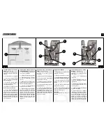
FORATURA DELLA PARETE
Come prima operazione occorre in-
dividuare nella parete il punto cor-
retto dove eseguire il foro di diame-
tro 60 mm, in funzione del posizio-
namento stabilito per le due unità
che compongono il prodotto. Prima
di procedere alla foratura, Vi consi-
gliamo di effettuare un’accurato esa-
me della parete per evitare di
lesionare strutture portanti o impianti
della Vostra abitazione (travi, pilastri,
tubazioni idrauliche, cavi elettrici,
ecc).
AVVERTENZE:
•
Prima di procedere ad effet-
tuare l’operazione di sconnes-
sione delle linee togliete l’alimen-
tazione elettrica dell’apparecchio
mediante l’estrazione della spina
del cavo di alimentazione dalla
presa di corrente.
•
Prima di far passare il connet-
tore rapido attraverso il foro che
avete praticato nella parete è in-
dispensabile proteggerlo con l’ap-
posito tappo dato in dotazione,
per evitare che polvere o impuri-
tà si depositino sulla parte inter-
na dello stesso. Lo sporco che si
verrebbe a trovare all’interno del
circuito del refrigerante (una vol-
ta ricollegate le linee) é gravemen-
te dannoso per il nostro climatiz-
zatore.
•
Non accendere assolutamen-
te l’apparecchio con la linea di
collegamento staccata. In caso
contrario si possono determina-
re gravi pericoli per la sicurezza
oltre a danni importanti al clima-
tizzatore.
INSTALLATION INSTRUCTIONS,
DRILLING A HOLE IN THE WALL
DRILLING THE WALL
The first thing to do is find the best
place on the wall to make a 60 mm
diameter hole, depending on the
position you have chosen for the
two units. Before drilling the hole
check carefully that nothing will be
d a m a g e d b y i t ( b e a m s , p i l l a r s ,
water pipes, electrical wires, etc.).
CAUTION:
•
B e f o r e d i s c o n n e c t i n g t h e
lines, take the appliance’s power
plug out of the mains socket.
•
B e f o r e p u t t i n g t h e q u i c k
coupling through the hole you
have just made in the wall, put a
protective cap on it to stop dust
and other impurities from getting
inside. Any dirt that gets inside
the coolant circuit (once the lines
have been reconnected) would
b e e x t r e m e l y h a r m f u l t o t h e
conditioner.
•
U n d e r n o c i r c u m s t a n c e s
must you switch the appliance on
i f t h e c o n n e c t i o n l i n e i s
disconnected. If you do not only
is it extremely hazardous for per-
s o n a l s a fe t y bu t i t c o u l d a l s o
seriously damage the appliance.
INSTRUCCIONES PARA LA
INSTALACIÓN CON ORIFICIO EN
LA PARED
TALADRADO DE LA PARED
La primera operación es hallar el pun-
to correcto donde se desea practicar
el orificio de 60 mm de diámetro, en
función del posicionamiento
establecido para las dos unidades que
componen el producto. Antes de iniciar
el taladrado, les aconsejamos
examinar atentamente la pared para
evitar dañar estructuras portantes o
instalaciones (travesaños, pilares,
conductos hidráulicos, cables
elécticos, etc.)
ADVERTENCIAS:
•
Antes de desconectar las líneas
quiten la alimentación eléctrica del
aparato, para ello desenchufen el
cable de alimentación de la toma de
corriente.
•
Antes de hacer pasar el
conector rápido a través del orificio
que han practicado en la pared, es
indispensable protegerlo con el
adecuado trapo en dotación para
evitar que el polvo o impurezas se
depositen en la parte interna del
mismo. La suciedad que se
introduciría en el interior del circui-
to del refrigerante (una vez
conectadas de nuevo las líneas) es
muy perjudicial para nuestro
climatizador
•
Por ningún motivo enciendan el
aparato con la línea de conexión
desconectada, en caso contrario se
pueden determinar graves peligros
para la seguridad así como
importantes daños al climatizador.
AVVERTENZA IMPORTANTE:
Le operazioni sotto elencate
devono essere eseguite solo da
personale specializzato ed in
possesso dei requisiti profes-
sionali per effettuare questo
tipo di lavoro.
MISE EN GARDE IMPORTANTE:
Les opérations ci-dessous doivent
être effectuées seulement par un
personnel spécialisé et
spécialement formé pour ce type
de travail.
IMPORTANT:
T h e p r o c e d u r e s d e s c r i b e d
below must only be done by
qualified personnel and who
h a v e t h e p r o f e s s i o n a l
knowledge required for such a
job.
WICHTIGER HINWEIS:
Die nachstehend beschriebenen
Arbeitsgänge sind ausschließlich
Fachpersonal vorbehalten, das
d i e n ö t i g e n K e n n t n i s s e z u r
Ausführung dieser Arbeit besitzt.
ADVERTENCIA IMPORTANTE:
L a s o p e r a c i o n e s q u e s e
describen a continuación deben
s e r e f e c t u a d a s ú n i c a y
exclusivamente por personal
especializado y con los requisitos
profesionales para efectuar este
tipo de trabajo.
BELANGRIJKE WAARSCHUWING:
De hieronder vermelde
werkzaamheden mogen uitsluitend
door gespecialiseerd personeel
uitgevoerd worden dat in het bezit is
van de nodige vakkundige vereisten
om dit soort werkzaamheden uit te
kunnen voeren.
Summary of Contents for NovEcos Split 11
Page 27: ...27...
Page 28: ...COD 273107B Edizione 1G...