Page: 52
Service Guide OF2200/2400/2600
Chapter 2 Failure Analysis
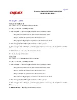
Checking PC1 and PC2
Okifax 2200 / Okifax 2400
This unit has two PC1 sensors and one PC2 sensor.
To check the sensors, follow this procedure.
1. Place the positive lead from a digital multimeter at the points listed below.
PC1 (Document Detect Sensor): Main Control Board CN 12, Pin 2
PC1 (B4 Width Sensor): Main Control Board CN 12, Pin 8
PC2 (Paper Leading Edge Sensor): Main Control Board CN 12, Pin 5
2. Place the negative lead of the digital multimeter on frame ground.
3. While making contact with the pin , press the appropriate lever. The voltage should go from +5 vdc to 0
vdc.
4. Release the lever. The voltage should return to +5 vdc.
5. If necessary, replace the sensor.
Okifax 2600
This unit has three PC1 sensors and one PC2 sensor.
To check the sensors, follow this procedure.
1. Place the positive lead from a digital multimeter at the points listed below.
PC1 (Document Detect Sensor): Main Control Board CN 12, Pin 2
PC1 (B4 Width Sensor): Main Control Board CN 12, Pin 8
PC1 (A3 Width Sensor): Main Control Board CN 12, Pin 11
PC2 (Paper Leading Edge Sensor): Main Control Board CN 12, Pin 5
2. Place the negative lead of the digital multimeter on frame ground.
3. While making contact with the pin , press the appropriate lever. The voltage should go from +5 vdc to 0
vdc.
4. Release the lever. The voltage should return to +5 vdc.
Summary of Contents for OF2200
Page 87: ...Partner Exchange BPX for any updates to this material http bpx okidata com...
Page 255: ...Page 151 Service Guide OF2200 2400 2600 Chapter A Board Diagrams A 2 INDEX TO CHARTS...
Page 256: ......
Page 259: ......
Page 262: ......
Page 265: ......
Page 268: ......
Page 273: ......
Page 276: ......
Page 279: ......
Page 284: ...Partner Exchange BPX for any updates to this material http bpx okidata com...
Page 285: ...Page 162 Service Guide OF2200 2400 2600 Chapter A Board Diagrams Okifax 2200 1 of 5...
Page 286: ......
Page 288: ...Page 163 Service Guide OF2200 2400 2600 Chapter A Board Diagrams Okifax 2200 2 of 5...
Page 289: ......
Page 291: ...Page 164 Service Guide OF2200 2400 2600 Chapter A Board Diagrams Okifax 2200 3 of 5...
Page 292: ......
Page 297: ......
Page 299: ...Page 168 Service Guide OF2200 2400 2600 Chapter A Board Diagrams Okifax 2400 2600 2 of 6...
Page 300: ......
Page 302: ...Page 169 Service Guide OF2200 2400 2600 Chapter A Board Diagrams Okifax 2400 2600 3 of 6...
Page 303: ......
Page 307: ...Page 172 Service Guide OF2200 2400 2600 Chapter A Board Diagrams Okifax 2400 2600 6 of 6...
Page 308: ......
Page 317: ......
Page 320: ......
Page 323: ......
Page 326: ......
Page 329: ......
Page 333: ......
Page 337: ......
Page 340: ......
Page 344: ......
Page 348: ......
Page 352: ......
Page 355: ......
Page 359: ......
Page 363: ......
Page 367: ......
Page 371: ......
Page 374: ......
Page 380: ......
Page 387: ...Page 199 Service Guide OF2200 2400 2600 Chapter B Illustrated Parts...
Page 389: ...Page 200 Service Guide OF2200 2400 2600 Chapter B Illustrated Parts...
Page 391: ...Page 201 Service Guide OF2200 2400 2600 Chapter B Illustrated Parts...
Page 395: ...Page 202 Service Guide OF2200 2400 2600 Chapter B Illustrated Parts UST500...

