Page: 31
Service Guide OF2200/2400/2600
Chapter 1 Principles of Operation
1.3 RECEIVER THEORY OF OPERATION
1.3.01 Operator Panel
Through the operator panel, the user initiates manual receive operations and sets auto-answer options.
1.3.02 Line Interface Board
The line interface board provides the RJ-11 connection used to receive data from the PSTN, PBX, or
Leased Line.
1.3.03 Network Control Board (NCU)
The network control unit receives the modulated data from the line interface board and sends it to the
modem (located on the main control board). The operation of the network control unit in the receive mode
is very similar to the transmit mode. However, during receive operations, the network control unit also
functions as an amplifier for the received signal.
1.3.04 Modem
The modem demodulates the data from the G3 (14.4, 12, 9.6, 7.2, 4.8, or 2.4K bps) scheme that was
determined during handshaking. The data is then sent to the RAM memory for temporary storage. The
storage time is dependent on whether the machine is printing real-time or from memory.
1.3.05 Decoder
The decoder decodes the MH, MR, or MMR data from the RAM into lines of picture data that are 1,728
bits in length. After the data has been received, demodulated, and decoded, it is transferred to the printer
control board.
1.3.06 Document Size
Since the available printing area of the printer is smaller than the paper size, document contents may be
missed on both sides of the paper, or a document image having the same length as the printing paper
may be split into separate pages during printing. To prevent this, the unit automatically sets the proper
reduction ratio within the range of 76 to 100% if the RX REDUCTION function has been set ON. If a
received document image is longer than the available printing length, the excess part of the image is
eliminated. If the SPLIT PRINT function has been set ON, the excess image will be printed on the next
page.
Copyright 1997, Okidata, Division of OKI America, Inc. All rights reserved. See the OKIDATA Business
Partner Exchange (BPX) for any updates to this material. (http://bpx.okidata.com)
Summary of Contents for OF2200
Page 87: ...Partner Exchange BPX for any updates to this material http bpx okidata com...
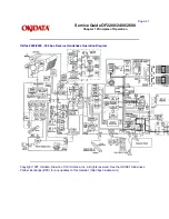
Page 255: ...Page 151 Service Guide OF2200 2400 2600 Chapter A Board Diagrams A 2 INDEX TO CHARTS...
Page 256: ......
Page 259: ......
Page 262: ......
Page 265: ......
Page 268: ......
Page 273: ......
Page 276: ......
Page 279: ......
Page 284: ...Partner Exchange BPX for any updates to this material http bpx okidata com...
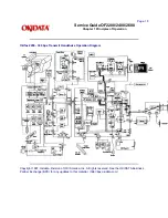
Page 285: ...Page 162 Service Guide OF2200 2400 2600 Chapter A Board Diagrams Okifax 2200 1 of 5...
Page 286: ......
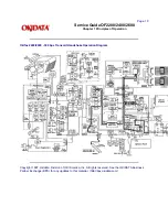
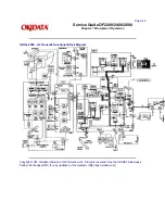
Page 288: ...Page 163 Service Guide OF2200 2400 2600 Chapter A Board Diagrams Okifax 2200 2 of 5...
Page 289: ......
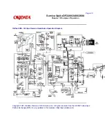
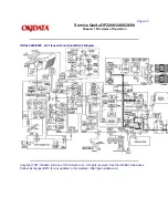
Page 291: ...Page 164 Service Guide OF2200 2400 2600 Chapter A Board Diagrams Okifax 2200 3 of 5...
Page 292: ......
Page 297: ......
Page 299: ...Page 168 Service Guide OF2200 2400 2600 Chapter A Board Diagrams Okifax 2400 2600 2 of 6...
Page 300: ......
Page 302: ...Page 169 Service Guide OF2200 2400 2600 Chapter A Board Diagrams Okifax 2400 2600 3 of 6...
Page 303: ......
Page 307: ...Page 172 Service Guide OF2200 2400 2600 Chapter A Board Diagrams Okifax 2400 2600 6 of 6...
Page 308: ......
Page 317: ......
Page 320: ......
Page 323: ......
Page 326: ......
Page 329: ......
Page 333: ......
Page 337: ......
Page 340: ......
Page 344: ......
Page 348: ......
Page 352: ......
Page 355: ......
Page 359: ......
Page 363: ......
Page 367: ......
Page 371: ......
Page 374: ......
Page 380: ......
Page 387: ...Page 199 Service Guide OF2200 2400 2600 Chapter B Illustrated Parts...
Page 389: ...Page 200 Service Guide OF2200 2400 2600 Chapter B Illustrated Parts...
Page 391: ...Page 201 Service Guide OF2200 2400 2600 Chapter B Illustrated Parts...
Page 395: ...Page 202 Service Guide OF2200 2400 2600 Chapter B Illustrated Parts UST500...

