background image

Page: 205

Service Guide OF2200/2400/2600

Chapter C Installation of Options


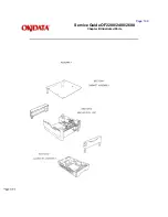
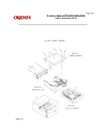
C.2.02 UST-500 (Second Paper Cassette Unit)

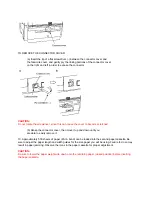
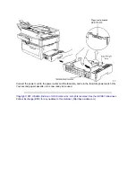
The second cassette unit comes with a second front cover and facsimile connector cable.

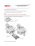
1. Turn the facsimile power switch OFF and remove the AC power cord.

NOTE:
Unplug the AC power cord from the power outlet first and then from the facsimile.

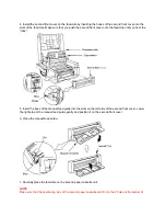
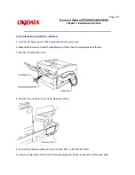
2. Remove the first cassette. Open the manual feed guide, and remove it by gently flexing it on the right 
side. Observe the way the guide is removed, as it will be re-installed later.

3. Open the document table and copy stacker.

Summary of Contents for OF2200

Page 1: ...g Manual 09 17 97 Note This Adobe Acrobat version of the Okidata Service Training Manual was built with the pictures rendered at 300 dpi which is ideal for printing but does not view on most displays...

Page 2: ...2 Transmitter Theory Of Operation 17 Okifax 2200 300 Bps Transmit Handshake Operation Diagram 18 Okifax 2400 2600 300 Bps Transmit Handshake Operation Diagram 19 Okifax 2200 300 Bps Receive Handshake...

Page 3: ...P 08 Reception Problem 56 RAP 09 Scan Operation Test Failure 57 RAP 10 LED Test Failure 58 RAP 11 Tone Send Test Failure 59 RAP 12 High Speed Modem Test Failure 60 RAP 13 Multi Frequency Send Test Fai...

Page 4: ...st Activity Report 97 2 7 03 Protocol Dump 98 Facsimile Control Field Conversion Table 99 2 8 Resets 100 2 8 01 General Information 101 2 8 02 Toner Counter Reset 102 2 8 03 Drum Counter Reset 103 2 8...

Page 5: ...d Second Tray Interface Board 137 3 2 20 Lower Base Assembly 138 3 2 21 Stacker Cover And Led Head 139 3 2 22 Feed Guide Eject Roller And Fusing Unit Assemblies 140 3 2 23 Motor Assembly Resist Motor...

Page 6: ...initions Of Terms 174 B 1 03 Parts Ordering Information 175 B 2 Charts 176 B 2 01 Cabinet Assembly 1 Of 2 177 B 2 02 Cabinet Assembly 2 Of 2 178 B 2 03 Control Panel Assembly Okifax 2200 179 B 2 04 Co...

Page 7: ...l Unit 201 B 2 34 Section 3 Cassette Assembly 202 C Installation of Options C 1 Overview 203 C 2 Option Installation 204 C 2 02 UST 500 Second Paper Cassette Unit 205 UST 500 Testing Procedure 206 C 2...

Page 8: ...99 Facsimile Number 609 235 2600 ext 7034 Okilink Login Name Technical Training OKI is a registered trademark of Oki Electric Industry Company Ltd marques deposee de Oki Electric Industry Company Ltd...

Page 9: ...This module contains three sections Transmitter Theory of Operation Receiver Theory of Operation LED Printer Theory of Operation Copyright 1997 Okidata Division of OKI America Inc All rights reserved...

Page 10: ...eration 1 1 01 Compatibility The facsimile machine operates as a Group 3 G3 facsimile device Copyright 1997 Okidata Division of OKI America Inc All rights reserved See the OKIDATA Business Partner Exc...

Page 11: ...take place at the same time However documents can be prepared for transmission while the machine is engaged in message reception These documents will be automatically transmitted upon completion of t...

Page 12: ...r for 4800 2400 bps operation CCITT Standard for V 17 14400 12000 bps Okifax 2400 2600 only CCITT Standard for V 33 14400 12000 bps Okifax 2400 2600 only The low speed 300 bps modem which is used for...

Page 13: ...mber of errors detected during the reception of a single page exceeds 10 of the data on the transmitted page it will return a Retrain Negative RTN signal to the transmitting station upon termination o...

Page 14: ...ine The other connects to an external telephone A separate modular jack is provided for connection of the handset The unit will control the switching between the handset or the external telephone and...

Page 15: ...ified Read uses a comparison technique The line being coded is compared to the previous line and differences are noted Codes are then assigned to reflect the differences between the two lines If no er...

Page 16: ...canned in approximately three seconds Once the documents are stored in memory the transmission is initiated without requiring additional user action Okifax 2200 Quick Scan 7 6 seconds per page Standar...

Page 17: ...cal The following major mechanical assemblies make up the facsimile machine Automatic Document Feeder ADF Unit Scan Unit Printer Unit Copyright 1997 Okidata Division of OKI America Inc All rights rese...

Page 18: ...ctrical assemblies make up the facsimile machine Main Control Board DFCU MCNT Printer Control Board DFPU PCNT Network Control Board NCU Operator Panel Assembly Not Shown Power Supply Unit Not Shown Me...

Page 19: ...Copyright 1997 Okidata Division of OKI America Inc All rights reserved See the OKIDATA Business Partner Exchange BPX for any updates to this material http bpx okidata com...

Page 20: ...pter 1 Principles of Operation Okifax 2200 Copy Function Block Diagram Copyright 1997 Okidata Division of OKI America Inc All rights reserved See the OKIDATA Business Partner Exchange BPX for any upda...

Page 21: ...er 1 Principles of Operation Okifax 2400 2600 Copy Function Block Diagram Copyright 1997 Okidata Division of OKI America Inc All rights reserved See the OKIDATA Business Partner Exchange BPX for any u...

Page 22: ...1 Principles of Operation Okifax 2200 Report Print Function Block Diagram Copyright 1997 Okidata Division of OKI America Inc All rights reserved See the OKIDATA Business Partner Exchange BPX for any...

Page 23: ...Principles of Operation Okifax 2400 2600 Report Print Function Block Diagram Copyright 1997 Okidata Division of OKI America Inc All rights reserved See the OKIDATA Business Partner Exchange BPX for a...

Page 24: ...ive Called Subscriber Identification CSI from the distant station After reading the document pages and storing the image data in memory the machine begins the handshake with the distant station If the...

Page 25: ...rinciples of Operation Okifax 2200 300 bps Transmit Handshake Operation Diagram Copyright 1997 Okidata Division of OKI America Inc All rights reserved See the OKIDATA Business Partner Exchange BPX for...

Page 26: ...ciples of Operation Okifax 2400 2600 300 bps Transmit Handshake Operation Diagram Copyright 1997 Okidata Division of OKI America Inc All rights reserved See the OKIDATA Business Partner Exchange BPX f...

Page 27: ...rinciples of Operation Okifax 2200 300 bps Receive Handshake Operation Diagram Copyright 1997 Okidata Division of OKI America Inc All rights reserved See the OKIDATA Business Partner Exchange BPX for...

Page 28: ...nciples of Operation Okifax 2400 2600 300 bps Receive Handshake Operation Diagram Copyright 1997 Okidata Division of OKI America Inc All rights reserved See the OKIDATA Business Partner Exchange BPX f...

Page 29: ...1 Principles of Operation Okifax 2200 G3 Transmit Functional Block Diagram Copyright 1997 Okidata Division of OKI America Inc All rights reserved See the OKIDATA Business Partner Exchange BPX for any...

Page 30: ...Principles of Operation Okifax 2400 2600 G3 Transmit Functional Block Diagram Copyright 1997 Okidata Division of OKI America Inc All rights reserved See the OKIDATA Business Partner Exchange BPX for a...

Page 31: ...and other data and interfaces in all areas of the operation of the machine The panel consists of an LCD display two rows of 20 characters a numeric key pad nine LED indicators and function keys The fu...

Page 32: ...tected when the PC2 lever is released If another document is on the feeder the process is repeated The Okifax 2200 2400 2600 also contain a B4 paper width sensor PC1 The Okifax 2600 has an additional...

Page 33: ...wever the machine can be modified for longer transmissions See Transmitting Long Documents in the Users Documentation Transmission will stop and a line disconnect will occur if the end of the document...

Page 34: ...ly The use of MH only or both MH and MR is determined by a function setting Data is then stored in the FIFO area in one byte units Fill bits are inserted if the length of one encoded line is less than...

Page 35: ...e that was determined during handshaking between the local machine and the remote receiver Modulation is the process of converting the digital output of the scanner into an analog signal that can be t...

Page 36: ...ation Unit connection disconnection to the telephone line via the CML Relay Dial pulse generation PIS tone detection OFF HOOK detection Line Current Detector TX output signal attenuation normally 9 de...

Page 37: ...face Board The line interface board provides the RJ 11 connection used to transmit data to the PSTN PBX or Leased Line Copyright 1997 Okidata Division of OKI America Inc All rights reserved See the OK...

Page 38: ...orary storage The storage time is dependent on whether the machine is printing real time or from memory 1 3 05 Decoder The decoder decodes the MH MR or MMR data from the RAM into lines of picture data...

Page 39: ...r 1 Principles of Operation Okifax 2200 G3 Receive Operation Block Diagram Copyright 1997 Okidata Division of OKI America Inc All rights reserved See the OKIDATA Business Partner Exchange BPX for any...

Page 40: ...Principles of Operation Okifax 2400 2600 G3 Receive Operation Block Diagram Copyright 1997 Okidata Division of OKI America Inc All rights reserved See the OKIDATA Business Partner Exchange BPX for an...

Page 41: ...d controls the paper feed and paper transport functions It also activates the LED array diodes which leave a latent electrostatic image on the photosensitive drum This latent image is printed by fusin...

Page 42: ...gnal is sent to the main control board and the cover open routine is performed The message COVER OPEN will be displayed on the operator panel High Voltage Circuits The following voltages are generated...

Page 43: ...DC Fan The fan is controlled by the FAN ON P signal from the main control board via the printer control board In order for the facsimiles printer to operate the signal FAN SENSE N must be active NOTE...

Page 44: ...led by a single registration motor Turning the registration motor in the A direction drives the hopping roller Turning the registration motor in the B direction drives the registration roller The regi...

Page 45: ...Printing Process Overview Copyright 1997 Okidata Division of OKI America Inc All rights reserved See the OKIDATA Business Partner Exchange BPX for any updates to this material http bpx okidata com...

Page 46: ...redetermined length until the paper reaches the registration roller 1 5 03 Feeding Feeding transports paper through the printer After the completion of hopping the registration motor turns in a counte...

Page 47: ...The positive carriers are moved to the CTL by an electrical field acting on the image drum The negative carriers flow into the aluminum layer ground The positive carriers moved to the CTL combine wit...

Page 48: ...doctor blade forming a thin coat of toner on the developing roller surface 1 5 07 Transfer The transfer roller is made of a conductive sponge material The roller keeps the paper in constant contact w...

Page 49: ...The toner supply roller is charged to 450 vdc The developing roller is charged to 300 vdc 1 5 10 Printing Refer to the Printing Process Diagram Printing is accomplished as follows Approximately 1 3 Kv...

Page 50: ...turning a 400 watt halogen lamp ON The fusing temperature is controlled by a thermistor In the event of a thermistor failure a temperature fuse will OPEN turning off the quartz lamp and preventing eq...

Page 51: ...period of time However the paper has already passed over the paper sensor Paper Size Error The time interval between when the paper contacts the paper sensor and the outlet sensor determines which siz...

Page 52: ...Copyright 1997 Okidata Division of OKI America Inc All rights reserved See the OKIDATA Business Partner Exchange BPX for any updates to this material http bpx okidata com...

Page 53: ...ccur When the printer is powered ON paper is at inlet sensor 1 After the hopping operation is attempted three times the leading edge of the paper does NOT reach inlet sensor 1 Copyright 1997 Okidata D...

Page 54: ...or within a pre determined period of time The leading part of the paper does not reach the outlet sensor within a pre determined period of time after the paper has passed over the paper sensor Paper F...

Page 55: ...sitioned at the bottom of the toner well the toner sensor lever is magnetically attracted to the toner agitator This causes the toner sensor lever to be lifted from the path of the toner sensor During...

Page 56: ...ion Use the RAP Index to identify which RAP should be used to resolve the problem with the machine If you encounter a situation that is not addressed by the documentation in this kit please report the...

Page 57: ...ilable Refer to the Service Center Reference Guide for information on accessing Okilink II 2 2 03 Faxable Facts Okidata s Faxable Facts is an automated fax document retrieval system It is maintained b...

Page 58: ...to these requests Okilink II provides round table discussions on technical problems Errors and corrections in the training materials are listed in the Training Section of Okilink II The Technical Serv...

Page 59: ...nce ZIP Postal Code Country 5 Telephone and Fax Numbers with area country access codes 6 Product Name 7 Units Serial Number 8 Description of Problem 9 Document Name with page number or procedure with...

Page 60: ...unit Oil from your skin can cause fusing temperature variation 4 Do not expose the image drum to light for more than five minutes 5 Do not touch the transfer roller Touching the transfer roller may ca...

Page 61: ...ne jack at the rear of the unit Lift the handset and check for a dial tone If you do not hear one there may be a problem with your telephone line If you hear a dial tone you may be using the wrong dia...

Page 62: ...or dark ask the person sending the fax to change the TRANSMIT RESOLUTION and TYPE OF ORIGINAL Settings Copy a similar document to test your unit If the copy looks good the problem may be telephone lin...

Page 63: ...y days 19 Your received faxes sometimes look distorted If the received document is wider longer than the paper loaded in the paper cassette the unit will automatically reduce the width length of the d...

Page 64: ...er Volume Okifax 2400 2600 Technical Function 12 Change the No Paper Call Feature The unit warbles when it is out of paper Okifax 2200 User Function 11 Okifax 2400 2600 Not applicable Saves to memory...

Page 65: ...answering machine and it doesnt work Enable the Telephone Answering Device TAD Mode Okifax 2200 Technical Function 45 Okifax 2400 2600 TAD Mode is not used Copyright 1997 Okidata Division of OKI Ameri...

Page 66: ...problem is not resolved proceed to the next step 2 Use the RAP Index to find the RAP which is associated with the units problem 3 Go to the appropriate RAP 4 All of the RAPs will begin with a START St...

Page 67: ...Problem 09 Scan Operation Test Failure 10 LED Test Failure 11 Tone Send Test Failure 12 High Speed Modem Test Failure 13 Multi frequency Send Test Failure 14 Voice Message Test Failure 15 No Acoustic...

Page 68: ...Vertical Black Stripes 21E Repetitive Spaced Marks 21F Vertical White Stripes 21G Areas Missing 21H Poor Fusing Copyright 1997 Okidata Division of OKI America Inc All rights reserved See the OKIDATA B...

Page 69: ...rm the Print Test Are the results satisfactory NO Refer to RAP 03 YES Go to the next step listed below Is the ROM check OK NO Replace the ROM on the printer control board Then replace the ROM s on the...

Page 70: ...problem YES Refer to RAP 08 Reception Problem NO Verify symptom and refer to the appropriate RAP Copyright 1997 Okidata Division of OKI America Inc All rights reserved See the OKIDATA Business Partner...

Page 71: ...ELECT FUNCTION OT YES End of procedure NO Go to CHECK 1 CHECK 1 Is 5 vdc present at pins 7 8 14 15 of CN4 on the printer control board NO Go to CHECK 2 YES Is 5 vdc present at pin 2 of CN1 on the oper...

Page 72: ...board is properly connected If the problem remains replace the memory board Copyright 1997 Okidata Division of OKI America Inc All rights reserved See the OKIDATA Business Partner Exchange BPX for any...

Page 73: ...ppropriate RAP 20B C D or E NO Is PAPER JAM displayed on the LCD YES Refer to RAP 20F NO Go to the next step listed below Is NO TONER displayed on the LCD YES Perform each of the following until the p...

Page 74: ...rocedure NO Perform the Print Test Is the Print Test OK NO Refer to the RAP 21 YES Replace the printer control board Has the problem been resolved YES End of procedure NO Replace the main control boar...

Page 75: ...e problem is resolved Check PC2 Replace the main control board YES Go to the next step listed below Press the COPY key Is the copied document all black YES Verify that 12 vdc is present at Pin 9 of CN...

Page 76: ...te lever The voltage should go from 5 vdc to 0 vdc 4 Release the lever The voltage should return to 5 vdc 5 If necessary replace the sensor Okifax 2600 This unit has three PC1 sensors and one PC2 sens...

Page 77: ...If necessary replace the sensor Copyright 1997 Okidata Division of OKI America Inc All rights reserved See the OKIDATA Business Partner Exchange BPX for any updates to this material http bpx okidata c...

Page 78: ...ne cable and the exchange YES Check for closed network method of dialing dial rate YES Replace the problem unit with a known good unit Does the good unit dial NO Go to LOCATION PROBLEM YES Does DIALIN...

Page 79: ...lved YES End of procedure NO Contact Technical Support Copyright 1997 Okidata Division of OKI America Inc All rights reserved See the OKIDATA Business Partner Exchange BPX for any updates to this mate...

Page 80: ...Function 57 Has the problem been resolved YES End of procedure NO Set SHORTEN PROTOCOL to OFF Okifax 2200 Technical Function 08 Okifax 2400 2600 Technical Function 76 Has the problem been resolved YE...

Page 81: ...hnical Function 13 Okifax 2400 2600 9600 bps Technical Function 86 Has the problem been resolved YES End of procedure NO Replace the problem unit with a known good unit Follow the preceding steps Does...

Page 82: ...all Is the closed network ON Is the remote phone number registered in one touch keys or three digit auto dial codes YES Is machine in the auto receive mode If not place the unit in auto receive mode b...

Page 83: ...s the problem been resolved YES End of procedure NO Contact Technical Support Copyright 1997 Okidata Division of OKI America Inc All rights reserved See the OKIDATA Business Partner Exchange BPX for a...

Page 84: ...0 Has the problem been resolved YES End of procedure NO Set CED DIS INTERVAL to 1 5 seconds Okifax 2200 Technical Function 15 Okifax 2400 2600 Technical Function 79 Has the problem been resolved YES E...

Page 85: ...00 2600 9600 bps Technical Function 86 Replace the problem unit with a known good unit Then repeat the preceding procedures Does the replaced unit receive normally NO Check the line and the network of...

Page 86: ...m connector CN4 on the printer control board and leave the other end connected to CN2 on the power supply board Voltage measurements should be taken from this cable Check 12 vdc at Pin 9 If 12 vdc is...

Page 87: ...Partner Exchange BPX for any updates to this material http bpx okidata com...

Page 88: ...C YES End of procedure NO Replace the operator panel board Has the problem been resolved YES End of procedure NO Check the connection cable between the main control board and the operator panel unit H...

Page 89: ...Okifax 2400 2600 Technical Function 10 NO Modify the appropriate Technical Function YES Is CN3 Speaker Harness connected to CN3 of the main control board YES Replace the main control board NO Connect...

Page 90: ...12 vdc on the main control board 12 vdc present at CN5 Pin 14 12 vdc present at CN5 Pin 15 Do 12 vdc and 12 vdc appear at these points NO Disconnect the cable from CN4 of the printer control board an...

Page 91: ...he cable from CN4 of the printer control board and measure the voltage at pin 14 and 15 of the connecting cable If 12 vdc are not present replace the power supply board Check the cables and the route...

Page 92: ...MF Send Test Place the oscilloscope probe on pin 1 of CN3 on the main control board Is a 15 v analog signal present YES Replace the speaker NO Replace the main control board Is the problem resolved YE...

Page 93: ...Okifax 2200 User Function 05 Okifax 2400 2600 Technical Function 10 NO Set Monitor Volume to LOW or HIGH YES Replace the main control board Has the problem been resolved YES End of procedure NO Replac...

Page 94: ...or Volume been set to LOW or HIGH Okifax 2200 User Function 05 Okifax 2400 2600 Technical Function 10 NO Set Monitor Volume to LOW or HIGH YES Replace the main control board Has the problem been resol...

Page 95: ...r 1 Printer Control Board 2 Scan Motor YES Is the control panel unit properly closed NO Properly close the control panel unit YES Is the leading edge of document curled or folded YES Load a document t...

Page 96: ...Copyright 1997 Okidata Division of OKI America Inc All rights reserved See the OKIDATA Business Partner Exchange BPX for any updates to this material http bpx okidata com...

Page 97: ...paration rubber assembly return to its original position when pushed NO Check the ADF spring the tension arm and the back up plate YES Replace the separation rubber Has the problem been resolved YES E...

Page 98: ...Is the thickness within specifications Multiple documents 0 06 to 0 13 mm Single documents 0 05 to 0 15 mm NO Use documents of the proper specification YES Are the documents normal NO Use a carrier s...

Page 99: ...step Is the ADF roller or the sub roller dirty YES Clean them NO Replace the following in the listed order ADF Roller Sub Roller Feed Rollers Pinch Rollers End of procedure Copyright 1997 Okidata Divi...

Page 100: ...rame assembly YES Does the unit feed the document about 7 cm then stop with SELECT LOCATION displayed on the LCD NO Perform each of the following until the problem is resolved 1 Check PC2 Refer to RAP...

Page 101: ...within length specified For 5 clear obstacles from the document path NO Is the paper path blocked YES Clear the paper path NO Are the parts in the paper path worn or damaged YES Replace them NO Are t...

Page 102: ...M AND STOP Engine controller error ROM RAM error 20C PRINTER ALARM 3 TEL CONFIRM AND STOP Fan motor rotation error 20D PRINTER ALARM 4 TEL CONFIRM AND STOP Fuser unit thermal error 20E Recording Paper...

Page 103: ...ed YES Is the cover open switch connector out of position YES Connect the cover open switch connector NO Refer to Action Item 2 NO Check the power supply at CN4 Pins 1 2 and 3 for 38 vdc Refer to Appe...

Page 104: ...O Refer to Action Item 3 YES Are the connections of the interface cable between the main control board CN11 and the printer control board CN10 correctly made NO Correctly make the connections YES Refe...

Page 105: ...n the LCD display Power OFF the unit then power ON Does PRINTER ALARM 2 remain on the LCD display NO Refer to Action Item 5 YES Refer to Action Item 6 Copyright 1997 Okidata Division of OKI America In...

Page 106: ...Has the fan motor stopped NO Refer to Action Item 7 YES Is the fan motor connector properly connected to the printer control board NO Connect the fan motor connector properly YES Refer to Action Item...

Page 107: ...led Refer to the Action Items Diagram NO Adjust the contacts as necessary YES Refer to Action Item 9 Replace the printer control board NO Does PRINTER ALARM 4 occur approximately 60 seconds after powe...

Page 108: ...Copyright 1997 Okidata Division of OKI America Inc All rights reserved See the OKIDATA Business Partner Exchange BPX for any updates to this material http bpx okidata com...

Page 109: ...ize for appropriate cassette YES Does the same error occur frequently NO Remove the jammed paper YES Does the error occur while paper is in the paper cassette YES Refer to Action Item 10 NO Does the e...

Page 110: ...PER REPLACE PAPER appears on the LCD display Has the paper cassette been loaded YES Load recording paper NO Refer to Action Item 14 Copyright 1997 Okidata Division of OKI America Inc All rights reserv...

Page 111: ...7 Check fan motor printer control board connectors power supply voltages 8 Replace fan motor printer control board power supply board 9 Check electrical connection between power supply board and the c...

Page 112: ...Copyright 1997 Okidata Division of OKI America Inc All rights reserved See the OKIDATA Business Partner Exchange BPX for any updates to this material http bpx okidata com...

Page 113: ...x to Image Problems Symptom Reference Figure Flowchart Number Poor Print Quality images are Figure A 21A light or blurred as a whole Dark Background Density Figure B 21B Blank Output Figure C 21C Vert...

Page 114: ...Copyright 1997 Okidata Division of OKI America Inc All rights reserved See the OKIDATA Business Partner Exchange BPX for any updates to this material http bpx okidata com...

Page 115: ...ic printing NO Use xerographic paper YES Is the LED head dirty YES Clean it NO Are the LED head and cable properly connected Check the LED head connector and connector CN3 of the printer control board...

Page 116: ...lem been resolved YES End of procedure NO Replace the printer control board Copyright 1997 Okidata Division of OKI America Inc All rights reserved See the OKIDATA Business Partner Exchange BPX for any...

Page 117: ...YES Clean the roller NO Is the cleaning roller contact of the image drum clean and properly touching the high voltage contact assembly NO Clean Replace the high voltage contact assembly YES Replace t...

Page 118: ...Is the image drum cartridge touching the ground contact on the high voltage contact assembly NO Clean Replace the high voltage contact assembly and clean the image drum contacts YES Replace the LED h...

Page 119: ...RT Is the TONER LOW message displayed YES Add toner NO Replace the image drum cartridge Has the problem been resolved YES End of procedure NO Replace the LED head Has the problem been resolved YES End...

Page 120: ...tridge 3 71 inches 94 2 mm Image drum in image drum cartridge Replace the image drum cartridge 2 27 inches 58 mm Rollers in image drum cartridge Replace the image drum cartridge 1 56 inches 40 mm Repl...

Page 121: ...ly NO Clean Replace the high voltage contact assembly YES Replace the transfer roller Has the problem been resolved YES End of procedure NO Is the LED head properly installed Check the LED Head connec...

Page 122: ...ng roller image drum and charging roller clean and properly touching the contact assembly NO Clean Replace the high voltage contact assembly YES Replace the image drum cartridge Has the problem been r...

Page 123: ...Copyright 1997 Okidata Division of OKI America Inc All rights reserved See the OKIDATA Business Partner Exchange BPX for any updates to this material http bpx okidata com...

Page 124: ...r designed for use in xerographic paper YES Are the springs for the pressure roller functioning properly Do they compress when pushed NO Replace the springs YES Replace the printer control board Has t...

Page 125: ...g tests by using the numeric key pad 1 Self Diagnosis 2 Scan Operation CIS Calibration 3 LED Test 4 Tone Send Test 5 High Speed Modem Transmission Test 6 High Speed Modem Reception Test 7 Multi Freque...

Page 126: ...the test results will be printed Okifax 2200 2 5 minutes Okifax 2400 2600 90 seconds 4 Press SELECT FUNCTION to exit the test Interpret the report refer to the sample as follows 1 Pattern 1 All White...

Page 127: ...M card if installed 13 Printout of TX and RX Counters Copyright 1997 Okidata Division of OKI America Inc All rights reserved See the OKIDATA Business Partner Exchange BPX for any updates to this mater...

Page 128: ...kifax 2200 both the Service Bit and the Sensor Calibration MUST be ON On the Okifax 2400 2600 the Sensor Calibration must be ON Refer to RAP 09 if the Sensor Calibration Scanning Check fails NOTE The...

Page 129: ...ATING SENSOR CALIBRATION RESULT OK SCANNING CHECK YES NO 7 Press RIGHT ARROW to remove the document OR Press LEFT ARROW to run the Scanning Check Refer to Scanning Check from Point A 8 Press SELECT FU...

Page 130: ...st Okifax 2200 1 Press SELECT FUNCTION 2 Press COPY twice 3 Press LEFT ARROW twice 4 Press RIGHT ARROW 5 Load a sheet of white letter size paper in the document feed area 6 Press RIGHT ARROW 7 Press L...

Page 131: ...2400 2600 does not utilize the scanning check ADF Test Copyright 1997 Okidata Division of OKI America Inc All rights reserved See the OKIDATA Business Partner Exchange BPX for any updates to this mat...

Page 132: ...ng message will be displayed 3 LED TEST BLINKING In turn each LED will light for approximately one second the order listed below Okifax 2200 ALARM PHOTO EX FINE FINE STD DARK NORMAL LIGHT AUTOREC All...

Page 133: ...y will energize connecting the unit to the phone line Each frequency will be sent from the LINE terminal for about five seconds After the 1100 hz tone is sent the CML Relay will de energize automatica...

Page 134: ...Copyright 1997 Okidata Division of OKI America Inc All rights reserved See the OKIDATA Business Partner Exchange BPX for any updates to this material http bpx okidata com...

Page 135: ...CT FUNCTION 2 Press COPY twice 3 Press LEFT ARROW twice 4 Enter 5 from the numeric key pad 5 Press LEFT ARROW The following message will be displayed MODEM RATE XXXX YES NO XXXX Frequency 6 Press RIGH...

Page 136: ...played MODEM SEND TEST TX WW XX YY ZZZZ WW Data Rate XX Communication Duration in minutes YY Communication Duration in seconds ZZZZ Error Count 9 Press STOP to end the test 10 Press SELECT FUNCTION to...

Page 137: ...Press COPY twice 3 Press LEFT ARROW twice 4 Enter 6 from the numeric key pad 5 Press LEFT ARROW The following message will be displayed MODEM REC TEST Rec WW XX YY ZZZZ WW Data Rate XX Communication D...

Page 138: ...on in minutes YY Communication Duration in seconds ZZZZ Error Count 7 Press STOP to end the test 8 Press SELECT FUNCTION to exit the test Copyright 1997 Okidata Division of OKI America Inc All rights...

Page 139: ...T ARROW twice 4 Enter the appropriate number from the numeric pad Okifax 2200 7 Okifax 2400 2600 05 5 Press LEFT ARROW 6 Press each key of the ten key pad keys The multi frequency signal of the key wi...

Page 140: ...ARROW twice 4 Enter the appropriate number from the ten key pad Okifax 2200 8 Okifax 2400 2600 10 5 Press LEFT ARROW After approximately 30 seconds the test will print 6 Press STOP once to halt printi...

Page 141: ...EL FAX Mode Procedure 1 Press SELECT FUNCTION 2 Press COPY twice 3 Press LEFT ARROW twice 4 Enter the appropriate number from the ten key pad Okifax 2200 9 Okifax 2400 2600 09 5 Press LEFT ARROW The f...

Page 142: ...uides for further details The available reports are listed below 1 Active Memory Files 2 Activity 3 Auto Dial Directory 4 Box List 5 Cancel 6 Communication Codes 7 Configuration 8 Confirmation of Entr...

Page 143: ...us Service Codes 6xxxx and 9xxx Code Description 0000 Successful end of communication 1080 STOP key has been pressed while calling a remote fax 10A2 Busy tone detected 14A3 Second dial tone not detect...

Page 144: ...B1 Confidential Reception was specified by transmitter in Phase B but the amount of available memory was insufficient 29B6 In Confidential Reception the mail box specified by the transmitter is not se...

Page 145: ...Voltage reversal was detected because of line disconnection 90B1 Picture memory checksum error 90C1 Document removed prior to transmission 90C6 Normal or error free lines not received for 13 seconds 9...

Page 146: ...F error Defective interface between the main controller board and the printer interface board Copyright 1997 Okidata Division of OKI America Inc All rights reserved See the OKIDATA Business Partner Ex...

Page 147: ...The Service Bit is Technical Function 27 Okifax 2400 2600 The Service Parameter is Technical Function 91 Refer to Section 2 9 for information on setting Technical Functions Manual Generation 1 Press S...

Page 148: ...Copyright 1997 Okidata Division of OKI America Inc All rights reserved See the OKIDATA Business Partner Exchange BPX for any updates to this material http bpx okidata com...

Page 149: ...s CSI 02 Called Subscriber Identification DIS 01 Digital Identification Signal NSC 84 Non Standard Facilities Command CIG 82 Calling Subscriber Identification DTC 81 Digital Transmit Command NSS 44 C4...

Page 150: ...38 B8 Response to End of Retransmission FCD 60 Facsimile Coded Data PPS 7D FD Partial Page Signal PPR 3D BD Partial Page Request RCP 61 Return to Control for Partial Page RNR 37 B7 Receive Not Ready R...

Page 151: ...Okifax 2200 or the appropriate bit of the Service Parameter Okifax 2400 2600 must be set to ON before resetting any counters Okifax 2200 Technical Function 27 Okifax 2400 2600 Technical Function 91 R...

Page 152: ...cedure Okifax 2200 1 Press SELECT FUNCTION 2 Press RIGHT ARROW 3 Press LEFT ARROW 4 Enter the appropriate number from the numeric keypad 6 Print Counter 7 Drum Counter 8 Fuser Counter 9 Toner Counter...

Page 153: ...Toner 3 Drum 4 Fuser 4 Press SELECT FUNCTION to exit OR Enter the number of another counter to view Copyright 1997 Okidata Division of OKI America Inc All rights reserved See the OKIDATA Business Par...

Page 154: ...kifax 2400 2600 must be set to ON to reset this counter Refer to Module 2 9 Okifax 2200 1 Press SELECT FUNCTION 2 Press RIGHT ARROW twice 3 Enter 8 from the numeric keypad 4 Press LEFT ARROW The follo...

Page 155: ...EAR YES NO 5 Press LEFT ARROW The following message will be displayed ARE YOU SURE YES NO 6 Press LEFT ARROW to reset the toner counter 7 Press SELECT FUNCTION to exit the procedure Copyright 1997 Oki...

Page 156: ...fax 2400 2600 must be set to ON to reset this counter Refer to Module 2 9 Okifax 2200 1 Press SELECT FUNCTION 2 Press RIGHT ARROW twice 3 Enter 8 from the numeric keypad 4 Press LEFT ARROW The followi...

Page 157: ...yed 3 DRUM COUNT CLEAR YES NO 5 Press LEFT ARROW The following message will be displayed ARE YOU SURE YES NO 6 Press LEFT ARROW to reset the counter 7 Press SELECT FUNCTION to exit the procedure Copyr...

Page 158: ...be set to ON to reset this counter Refer to Module 2 9 Okifax 2200 1 Press SELECT FUNCTION 2 Press RIGHT ARROW twice 3 Enter 8 from the numeric keypad 4 Press LEFT ARROW The following message will be...

Page 159: ...CLEAR YES NO 5 Press LEFT ARROW The following message will be displayed ARE YOU SURE YES NO 6 Press LEFT ARROW to reset the counter 7 Press SELECT FUNCTION to exit the procedure Copyright 1997 Okidat...

Page 160: ...ration Report Auto Dial List One Touch List A System Reset clears the Random Access Memory RAM The Service Bit Okifax 2200 or the appropriate bit of the Service Parameter Okifax 2400 2600 must be set...

Page 161: ...TA CLR Press the 4 key CONFIG DATA CLR Press the 5 key TX PAGES CLR Press the 6 key RX PAGES CLR 7 Press LEFT ARROW The following message will be displayed ARE YOU SURE 8 Press LEFT ARROW to CLEAR the...

Page 162: ...wing message will be displayed Okifax 2200 FUNCTION NUMBER 01 45 Okifax 2400 2600 FUNCTION NUMBER 01 91 6 Enter the number of the desired technical function 01 not 1 7 Press RIGHT ARROW to select the...

Page 163: ...tinuous Polling Placing a document on the ADF tray selects the polling mode without operating the SELECT FUNCTION Key R Allows continuous loop RX poll of auto dial group OFF 07 MH Only Limits image co...

Page 164: ...nual reception OFF 19 Off Hook Bypass Allows communications to be established without having the handset installed OFF 20 Long Document TX Long Document Transmission Select R ON 60 minutes maximum R O...

Page 165: ...Okifax 2200 will wait for a remote station s answer 000 35 Receive in Memory when Low Toner Condition Exists Enables the Memory RX Function when a low toner condition exists ON 36 RX Error Message Pr...

Page 166: ...t ID Printing For security purposes enables disables the printing of the distant ID in the activity report This function applies to message confirmation reports confidential receive reports and power...

Page 167: ...or Report when Technical Functions 1 or 3 show a communication error in memory TX ON 05 Personal Box Reception Report Enables ON or disables OFF the automatic printing of the Reception Report when a c...

Page 168: ...fault transmission mode Settings a NORMAL LIGHT or DARK b STD FINE or EX FINE c PHOTO or non PHOTO if FINE is selected NORMAL STD and non PHOTO 15 Memory and Feeder Selection Switching Selects the tra...

Page 169: ...TSI CSI from the remote station are compared with the registered one touch and auto dial numbers of the local station If the numbers do not match the communication will disconnect OFF 22 Relay Station...

Page 170: ...te Okifax 2600 ONLY Touch Tone Mode Function 16 5 Confidential Relay Broadcast Okifax 2600 ONLY Touch Tone Mode Function 17 6 Polling Transmission to the touch tone caller Touch Tone Mode Function 21...

Page 171: ...more pages the end of the preceding page will be printed at the top of the following page Settings 5 mm 10 mm OFF 10 mm 37 Date and Time Printing Enables ON or disables OFF printing the local date and...

Page 172: ...Settings OFF ON Restrict Access ON Restrict Access OFF When Department ID is ON and Restrict Access is ON unit operation is restricted to authorized users Users must enter a pre registered code to op...

Page 173: ...opy reception starts OFF The copy is stopped when incoming call arrives and automatic restart of copy is not allowed 55 Select Language Selects the language for operator panel and print messages Setti...

Page 174: ...the exchange requirements Settings NORMAL GROUND or FLASH NORMAL 63 Access Digit Prefix dialing digits used by PBX to connect fax to the public line OFF 64 Telephone Fax Automatic Switch Over Timer Sp...

Page 175: ...Printer Mode Bell 212A XON XOFF or DTR Mode XON XOFF Stop Bit 1 or 2 bit 1 bit TX Rate 4 8 2 4 1 2 0 3 kpbs 4 8 kpbs 70 Not assigned 71 Not assigned 72 Not assigned 73 Not assigned 74 Line Monitor Con...

Page 176: ...or a CNG signal for the leased line mode PIS Procedure interrupt signal CNG Calling tone PIS 84 Sensor Calibration When set to ON the unit can perform a calibration of the scanner sensor CIS This set...

Page 177: ...ing an extra line of print between two consecutive original lines ON 91 Service Parameter The Service Parameter contains 24 bits which are modified through six hexadecimal numerals Refer to the Bit As...

Page 178: ...oner Counter Display 4 Service Default Report 5 Protocol Dump 6 Ring Response Time 7 Dial Parameters 8 Clearing the Printer Counters Procedure 1 Press SELECT FUNCTION 2 Press COPY twice 3 Press LEFT A...

Page 179: ...l number The Service Parameter enables or disables the following functions 1 Drum Counter Display 2 Fuser Counter Display 3 Toner Counter Display 4 Service Default Report 5 Protocol Dump 6 Ring Respon...

Page 180: ...XXXXX YES NO X Hexadecimal Numerals 10 Press RIGHT ARROW to access the desired Hexadecimal Numeral 11 Enter the desired Hexadecimal Code using the numeric keypad for codes 0 9 and the One Touch Keys f...

Page 181: ...age 110 Service Guide OF2200 2400 2600 Chapter 2 Failure Analysis Bit Assignments Table Service Parameter is assigned in 24 bits as listed below The default setting for the Service Parameter is 807800...

Page 182: ...Copyright 1997 Okidata Division of OKI America Inc All rights reserved See the OKIDATA Business Partner Exchange BPX for any updates to this material http bpx okidata com...

Page 183: ...answer the unit automatically switches back to the facsimile mode to allow the calling party to manually send a fax The TEL FAX Timer function controls how long the unit waits before switching back t...

Page 184: ...allows the unit to be controlled from a remote location through a touch tone keypad telephone or fax unit Refer to the Users Guide for further information Copyright 1997 Okidata Division of OKI Americ...

Page 185: ...Numeric Keypad 2 External Telephone 3 One Touch Keys 4 Auto Dial Keys The One Touch and Auto Dial Keys allow the operator to program numbers into the fax machines Refer to the Users Guide for further...

Page 186: ...00 There are 83 programmable User Functions in the Okifax 2400 2600 The operator can program set these functions to customize the operation of the unit Refer to the Users Guide for further information...

Page 187: ...Page 115 Service Guide OF2200 2400 2600 Chapter 2 Failure Analysis 2 13 02 Dual Access Combination Table Okifax 2400 2600 NOTE Dual Access is available ONLY with the Okifax 2400 and Okifax 2600 units...

Page 188: ...In this case copy operation does not automatically resume after completion of receive operation Available with some limitations Printing operation interrupted at end of the page and memory TX scanning...

Page 189: ...options are available 1 A document is loaded into the ADF 2 No document is loaded If a document is loaded go to DOCUMENT LOADED for the available options If a document is not loaded press SELECT FUNCT...

Page 190: ...LEFT ARROW Password is OK Press AUTO DIAL Enter the two digit number 01 70 to access each Auto Dial Setting Press copy twice Technical Program Access by pressing and holding COPY during Power ON Pres...

Page 191: ...Pages Clear 5 RX Pages Clear Press RIGHT ARROW Press LEFT ARROW to access Report Printout Press RIGHT ARROW to access User Program Report Printout Press LEFT ARROW to access reports Then enter the rep...

Page 192: ...Refer to User s Functions in the User s Guide 5 Data Programming Press LEFT ARROW to access programs Then enter the program number 1 Clock Adjustment 2 System Data Program Press RIGHT ARROW to access...

Page 193: ...ash Earth Normal Service Bit set ON Dial Tone Detect Service Bit set ON Auto Start 6 Program Password Press LEFT ARROW to access Mail Box No Mail Box Password 7 Department ID Prg Press LEFT ARROW to a...

Page 194: ...Copyright 1997 Okidata Division of OKI America Inc All rights reserved See the OKIDATA Business Partner Exchange BPX for any updates to this material http bpx okidata com...

Page 195: ...he facsimile unit is a xerographic device Cleaning procedures must be performed correctly if high print quality is to be achieved 3 1 02 Maintenance Tools The following tools are required to service t...

Page 196: ...treme care Integrated circuits microprocessors ROM and RAM can be destroyed by static electricity Do not place printed circuit boards directly on conductive surfaces Follow the recommended procedures...

Page 197: ...ere Reverse the procedure for the installation This Service Handbook lists the disassembly procedures for major components of the unit Be sure to read all notes cautions and warnings as they contain i...

Page 198: ...rum with toner cartridge NOTES Refer to Module 3 4 of this Service Handbook for cleaning details Refer to Module 2 8 of this Service Handbook for Toner and Drum Counter Information P N 53549709 Handse...

Page 199: ...2 18 100 Sheet Capacity P N 50105501 Stacker Universal Assembly RSPL B 2 01 Includes the items listed below P N N A Stacker Universal P N N A Sub Stacker Copyright 1997 Okidata Division of OKI America...

Page 200: ...table guide and the document guide cover pinion gear To replace any of these parts order the assembly 5 Remove the two screws that retain the rear cover 6 Remove the rear cover and the terminal cap c...

Page 201: ...able Guide Document P N N A Tray Sub Hopper P N N A Screw Copyright 1997 Okidata Division of OKI America Inc All rights reserved See the OKIDATA Business Partner Exchange BPX for any updates to this m...

Page 202: ...e document guide table 3 Remove the IC card cover by lifting up then out 4 Remove the two screws using a small flat screw driver detach the right side cover assembly by lifting up then out 5 Disconnec...

Page 203: ...Copyright 1997 Okidata Division of OKI America Inc All rights reserved See the OKIDATA Business Partner Exchange BPX for any updates to this material http bpx okidata com...

Page 204: ...ol unit by pulling it toward you 5 Disconnect the three connectors from the NCU U board 6 Remove the network control unit and package shelf P N 50106701 Package Shelf B 2 08 P N 55073401 PCB Line JU R...

Page 205: ...m the network control board towards the left side cover until the cables are free 5 Remove the two screws then detach the left side cover by lifting it up and outward 6 Remove the left side cover and...

Page 206: ...d remove the cradle cover 4 Remove the two screws on the underside of the cradle base 5 Use a small flat screw driver and detach the three hooks 6 Remove the cradle base P N 50317201 Cover Cradle RSPL...

Page 207: ...bles and take out the modular jack 3 Remove the two screws that retain the hook switch board 4 Remove the hook switch board 5 Detach the two connectors P N 55074002 PCB Hook Switch RSPL B 2 02 Copyrig...

Page 208: ...ard bracket from the connection board 4 Remove the four mounting screws B then remove the memory board from the bracket P N 51710401 Bracket DFME B 2 10 P N 55075201 PCB ME 250 2200 RSPL B 2 10 P N 55...

Page 209: ...Release the two hooks and remove the control panel assembly NOTE The longer scanner hinge is on the right side P N 50806301 Hinge Scanner R B 2 10 P N 50806302 Hinge Scanner L B 2 10 P N 50105601 Pan...

Page 210: ...P N N A Label Ten Key 2400 2600 B 2 04 P N N A Sheet Function 1 2600 B 2 04 P N 51013601 Guide Paper Upper RSPL B 2 16 P N 53071901 Cover One Touch RSPL B 2 03 04 P N 53072011 Sheet One Touch U 2400 2...

Page 211: ...Use needle nose pliers to remove the spring 6 Fold back the two adhesive static brushes 7 Remove the support plate 8 Remove the feed roller assembly 9 Slide out the pinch roller from the support plat...

Page 212: ...B 2 15 P N 50406801 Roller Feed Assembly RSPL B 2 12 Includes the items listed below P N N A Bearing B 2 12 P N N A Roller Feed 2 B 2 12 P N N A Gear Z21 B 2 12 P N N A Washer Compression B 2 12 P N...

Page 213: ...ed without removing the control panel assembly The separation rubber assembly includes the separation rubber separation mylar and tape 10 x 36mm To replace any of these parts order the assembly P N 53...

Page 214: ...over U 1 Perform procedure 3 2 09 2 Remove the two screws 3 Remove the cover U P N 53071701 Cover U RSPL B 2 10 Copyright 1997 Okidata Division of OKI America Inc All rights reserved See the OKIDATA B...

Page 215: ...he paper guide M 4 Remove the paper guide M 5 Remove the two screws then remove the two release springs 6 Detach the two release levers 7 Remove the sensor roller assembly and the sub roller assembly...

Page 216: ...below P N N A Bearing B 2 13 P N N A Shaft ADF B 2 13 P N N A Roller ADF Feed B 2 13 P N N A Gear Z28 B 2 13 P N N A Clutch B 2 13 P N N A Washer Compression B 2 12 P N 50407201 Roller Sensor Assembly...

Page 217: ...aning refer to Module 3 4 of this Service Handbook P N 51013501 Guide Paper E 2200 2400 RSPL B 2 10 P N 51013502 Guide Paper E 2600 RSPL B 2 10 P N 50708301 Stamp Verification 2400 2600 RSPL B 2 12 17...

Page 218: ...Copyright 1997 Okidata Division of OKI America Inc All rights reserved See the OKIDATA Business Partner Exchange BPX for any updates to this material http bpx okidata com...

Page 219: ...of this Service Handbook P N 50407502 Sensor Image B4 Assembly 2200 2400 RSPL B 2 14 Includes the items listed below P N N A Sensor B4 2200 2400 B 2 14 P N N A Plate Ground SR B 2 14 P N N A Holder Se...

Page 220: ...Copyright 1997 Okidata Division of OKI America Inc All rights reserved See the OKIDATA Business Partner Exchange BPX for any updates to this material http bpx okidata com...

Page 221: ...dbook P N 53345002 Frame Gear Assembly 2200 RSPL B 2 14 Includes the items listed below P N N A Gear Frame B 2 14 P N N A Gear Z17 26 B 2 14 P N N A Gear Z45 B 2 14 P N N A Gear Idle Z30 B 2 14 P N N...

Page 222: ...P N N A Screw B 2 14 Copyright 1997 Okidata Division of OKI America Inc All rights reserved See the OKIDATA Business Partner Exchange BPX for any updates to this material http bpx okidata com...

Page 223: ...the three connectors on the 2200 and 2400 units the OF 2600 has four connectors 3 Using a straight slot screwdriver open the sensor latches 4 Remove the PC1 sensors and the PC2 sensor 5 Push the two p...

Page 224: ...Copyright 1997 Okidata Division of OKI America Inc All rights reserved See the OKIDATA Business Partner Exchange BPX for any updates to this material http bpx okidata com...

Page 225: ...he release guide assembly 4 Open the stacker cover and release the inner cover 5 Remove the four screws and detach the right sub cover P N 53069701 Cover Inner RSPL B 2 05 P N 53071301 Cover Sub R RSP...

Page 226: ...Copyright 1997 Okidata Division of OKI America Inc All rights reserved See the OKIDATA Business Partner Exchange BPX for any updates to this material http bpx okidata com...

Page 227: ...ard and remove the connectors 4 Remove the main control board 5 Disconnect the connector 6 Remove the screw B then remove the second tray interface board P N 55076001 PCB MT 25 2200 B 2 11 P N 5507610...

Page 228: ...Copyright 1997 Okidata Division of OKI America Inc All rights reserved See the OKIDATA Business Partner Exchange BPX for any updates to this material http bpx okidata com...

Page 229: ...otor connectors CN1 CN2 and the LED head cable from connector CN3 of the printer control board 4 Remove the seven screws 5 Remove the lower base P N N A Screw B 2 05 P N N A Screw B 2 05 P N N A Screw...

Page 230: ...Copyright 1997 Okidata Division of OKI America Inc All rights reserved See the OKIDATA Business Partner Exchange BPX for any updates to this material http bpx okidata com...

Page 231: ...not to touch the lens portion of the LED head Under normal circumstances the PC connector should NOT be removed from the LED head If it is removed use caution NOT to lose the connector pins When the L...

Page 232: ...Copyright 1997 Okidata Division of OKI America Inc All rights reserved See the OKIDATA Business Partner Exchange BPX for any updates to this material http bpx okidata com...

Page 233: ...feed guide assembly 3 Using a flat blade screwdriver press the latch inward and hold while lifting the eject roller assembly up and out 4 Remove the four screws 5 Remove the fusing unit assembly NOTE...

Page 234: ...Copyright 1997 Okidata Division of OKI America Inc All rights reserved See the OKIDATA Business Partner Exchange BPX for any updates to this material http bpx okidata com...

Page 235: ...otor assembly 6 Remove the two idle gears and the reduction gear from the motor assembly 7 Remove the four screws B 8 Remove the resist motor and main motor from the motor assembly NOTE When lubricati...

Page 236: ...Copyright 1997 Okidata Division of OKI America Inc All rights reserved See the OKIDATA Business Partner Exchange BPX for any updates to this material http bpx okidata com...

Page 237: ...the printer unit 6 Lift the transfer roller from the gear side of the printer unit Then carefully remove the transfer roller and transfer roller gear NOTE Lubrication Lightly lubricate the channels o...

Page 238: ...Copyright 1997 Okidata Division of OKI America Inc All rights reserved See the OKIDATA Business Partner Exchange BPX for any updates to this material http bpx okidata com...

Page 239: ...mper arm Detach the damper gear 8 Remove the two idle gears CAUTION When lubricating refer to Module 3 5 of this Service Handbook Do NOT lubricate the sensor plates P N 50219601 Assembly Hopping Rolle...

Page 240: ...ring Registration Roller B 2 06 P N 53069101 Arm Stacker Cover Damper RSPL B 2 06 Copyright 1997 Okidata Division of OKI America Inc All rights reserved See the OKIDATA Business Partner Exchange BPX f...

Page 241: ...ove the connector 3 Remove the three screws A and the ground cable 4 Remove the line board 5 Remove the connectors and the four screws B then remove the network control board from the package shelf NO...

Page 242: ...Copyright 1997 Okidata Division of OKI America Inc All rights reserved See the OKIDATA Business Partner Exchange BPX for any updates to this material http bpx okidata com...

Page 243: ...e power supply board 3 Remove the two screws 4 Disconnect the fan cable from CN7 of the printer control board 5 Remove the remaining connectors from the printer control board 6 Remove the printer cont...

Page 244: ...Copyright 1997 Okidata Division of OKI America Inc All rights reserved See the OKIDATA Business Partner Exchange BPX for any updates to this material http bpx okidata com...

Page 245: ...ws B 5 Remove the power supply board contact assembly 6 Release the two hooks and detach the contact assembly 7 Release the hook and detach the cassette sensor plate then remove the sensor plate 8 Rem...

Page 246: ...F RSPL B 2 09 P N 51014201 Plate Base B 2 09 P N 51113110 Cork Friction B 2 09 P N 51710101 Bracket Inlet B 2 09 P N 51710201 Insulator B 2 09 P N 51710301 Insulator S B 2 09 P N 52202601 Tape Teflon...

Page 247: ...sette Lock B 2 08 P N N A Spring Lock B 2 08 P N 50806104 Rubber Foot B 2 08 P N N ALink Sheet R B 2 08 P N N A Spring Sheet B 2 08 P N 53345201 Block Link Pull RSPL B 2 08 P N N A Washer Universal B...

Page 248: ...When the main controller board is replaced Okifax 2200 3 When the printer controller board is replaced Okifax 2400 2600 LED Head Intensity Rating The last three numbers of the label on the LED head ar...

Page 249: ...0 Switch ON Copyright 1997 Okidata Division of OKI America Inc All rights reserved See the OKIDATA Business Partner Exchange BPX for any updates to this material http bpx okidata com...

Page 250: ...ths or as needed 1 Remove any dropped toner or dust 2 Clean inside and around the printer with a vacuum cleaner designed to pick up toner when necessary 3 4 02 LED Head The LED head should be cleaned...

Page 251: ...filter you may severely damage the vacuum cleaner Do NOT touch the transfer roller Touching the transfer roller may cause incomplete toner transfer resulting in faded output 3 4 04 Covers 1 Clean the...

Page 252: ...tem Disassembly Procedure ADF roller gear 3 2 13 All gears of the gear frame assembly 3 2 16 Transmit stepper motor gear 3 2 16 Eject roller assembly where roller shafts contact the assembly 3 2 22 Ej...

Page 253: ...the fins 3 2 25 Teeth of the reduction gear 3 2 26 Requires Dow Corning Molycoat HP 3001 high temperature conductive grease Copyright 1997 Okidata Division of OKI America Inc All rights reserved See t...

Page 254: ...n Firmware Fuses Jumpers Switches Sensors Test Points Where an item is not applicable the word NONE will be listed This Appendix also includes Interconnect Diagrams for the Okifax 2200 as well as the...

Page 255: ...Page 151 Service Guide OF2200 2400 2600 Chapter A Board Diagrams A 2 INDEX TO CHARTS...

Page 256: ......

Page 257: ...200 2400 2600 A 2 05 Power Supply Unit PWU 2200 2400 2600 A 2 06 Memory Board MT 25 2200 A 2 07 Memory Board DFME 2400 2600 A 2 08 Line Interface Board LINE 2200 2400 2600 A 2 09 Connector Board CB250...

Page 258: ...odulates data and generates multi frequency signals for tone dialing It amplifies signals and sends the amplified signals to a speaker The main control board houses an 8 MHz Microprocessor static RAM...

Page 259: ......

Page 260: ...Copyright 1997 Okidata Division of OKI America Inc All rights reserved See the OKIDATA Business Partner Exchange BPX for any updates to this material http bpx okidata com...

Page 261: ...verts serial receive data to parallel data modulates demodulates data and generates multi frequency signals for tone dialing It amplifies signals and sends the amplified signals to a speaker The main...

Page 262: ......

Page 263: ...Copyright 1997 Okidata Division of OKI America Inc All rights reserved See the OKIDATA Business Partner Exchange BPX for any updates to this material http bpx okidata com...

Page 264: ...rive the registration motor verification stamp clutch and transmit stepper motor drum motor and DC fan This board activates the LED Head in accordance with signals received from the main control board...

Page 265: ......

Page 266: ...Copyright 1997 Okidata Division of OKI America Inc All rights reserved See the OKIDATA Business Partner Exchange BPX for any updates to this material http bpx okidata com...

Page 267: ...lutch and transmit stepper motor drum motor and DC fan This board activates the LED Head in accordance with signals received from the main control board Firmware ROM Location O1A 256 Kbytes contains P...

Page 268: ......

Page 269: ...Copyright 1997 Okidata Division of OKI America Inc All rights reserved See the OKIDATA Business Partner Exchange BPX for any updates to this material http bpx okidata com...

Page 270: ...tion converts received analog data to digital signal levels generates dial pulses and detects incoming ring signals when a ring signal of 20 Hz at 25 Vrms is input to line terminals L1 and L2 Firmware...

Page 271: ...Copyright 1997 Okidata Division of OKI America Inc All rights reserved See the OKIDATA Business Partner Exchange BPX for any updates to this material http bpx okidata com...

Page 272: ...uses F1 6 3 amp AC line fuse F2 3 15 amp protects the 38 vdc circuitry F3 5 amp protects the 5 vdc circuitry Jumpers NONE Sensors PS1 Paper Exit Sensor PS2 Paper Sensor detects the leading edge of the...

Page 273: ......

Page 274: ...Copyright 1997 Okidata Division of OKI America Inc All rights reserved See the OKIDATA Business Partner Exchange BPX for any updates to this material http bpx okidata com...

Page 275: ...data picture memory for ECM send receive mode picture memory for memory transmission mode picture memory for the retransmission of data and image memory for reception in memory All system data is sto...

Page 276: ......

Page 277: ...Copyright 1997 Okidata Division of OKI America Inc All rights reserved See the OKIDATA Business Partner Exchange BPX for any updates to this material http bpx okidata com...

Page 278: ...mory for memory transmission mode picture memory for the retransmission of data and image memory for reception in memory A 4 8 Volt battery retains all of this information when AC power is disrupted o...

Page 279: ......

Page 280: ...Copyright 1997 Okidata Division of OKI America Inc All rights reserved See the OKIDATA Business Partner Exchange BPX for any updates to this material http bpx okidata com...

Page 281: ...2 09 Line Interface Board LINE Function This board sends and receives data from the telephone line Firmware NONE Fuses NONE Jumpers NONE Sensors NONE Switches SW1 Ring Volume Adjustment Three Position...

Page 282: ...Copyright 1997 Okidata Division of OKI America Inc All rights reserved See the OKIDATA Business Partner Exchange BPX for any updates to this material http bpx okidata com...

Page 283: ...10 Connector Board CB 250 Function This board connects the unit to the optional paper tray Firmware NONE Fuses NONE Jumpers NONE Sensors NONE Switches NONE Test Points NONE Copyright 1997 Okidata Divi...

Page 284: ...Partner Exchange BPX for any updates to this material http bpx okidata com...

Page 285: ...Page 162 Service Guide OF2200 2400 2600 Chapter A Board Diagrams Okifax 2200 1 of 5...

Page 286: ......

Page 287: ...Copyright 1997 Okidata Division of OKI America Inc All rights reserved See the OKIDATA Business Partner Exchange BPX for any updates to this material http bpx okidata com...

Page 288: ...Page 163 Service Guide OF2200 2400 2600 Chapter A Board Diagrams Okifax 2200 2 of 5...

Page 289: ......

Page 290: ...Copyright 1997 Okidata Division of OKI America Inc All rights reserved See the OKIDATA Business Partner Exchange BPX for any updates to this material http bpx okidata com...

Page 291: ...Page 164 Service Guide OF2200 2400 2600 Chapter A Board Diagrams Okifax 2200 3 of 5...

Page 292: ......

Page 293: ...Copyright 1997 Okidata Division of OKI America Inc All rights reserved See the OKIDATA Business Partner Exchange BPX for any updates to this material http bpx okidata com...

Page 294: ...00 2400 2600 Chapter A Board Diagrams Okifax 2200 4 of 5 Copyright 1997 Okidata Division of OKI America Inc All rights reserved See the OKIDATA Business Partner Exchange BPX for any updates to this ma...

Page 295: ...00 2400 2600 Chapter A Board Diagrams Okifax 2200 5 of 5 Copyright 1997 Okidata Division of OKI America Inc All rights reserved See the OKIDATA Business Partner Exchange BPX for any updates to this ma...

Page 296: ...Page 167 Service Guide OF2200 2400 2600 Chapter A Board Diagrams A 2 12 Interconnect Diagrams 2400 2600 Okifax 2400 2600 1 of 6...

Page 297: ......

Page 298: ...Copyright 1997 Okidata Division of OKI America Inc All rights reserved See the OKIDATA Business Partner Exchange BPX for any updates to this material http bpx okidata com...

Page 299: ...Page 168 Service Guide OF2200 2400 2600 Chapter A Board Diagrams Okifax 2400 2600 2 of 6...

Page 300: ......

Page 301: ...Copyright 1997 Okidata Division of OKI America Inc All rights reserved See the OKIDATA Business Partner Exchange BPX for any updates to this material http bpx okidata com...

Page 302: ...Page 169 Service Guide OF2200 2400 2600 Chapter A Board Diagrams Okifax 2400 2600 3 of 6...

Page 303: ......

Page 304: ...Copyright 1997 Okidata Division of OKI America Inc All rights reserved See the OKIDATA Business Partner Exchange BPX for any updates to this material http bpx okidata com...

Page 305: ...2400 2600 Chapter A Board Diagrams Okifax 2400 2600 4 of 6 Copyright 1997 Okidata Division of OKI America Inc All rights reserved See the OKIDATA Business Partner Exchange BPX for any updates to this...

Page 306: ...2400 2600 Chapter A Board Diagrams Okifax 2400 2600 5 of 6 Copyright 1997 Okidata Division of OKI America Inc All rights reserved See the OKIDATA Business Partner Exchange BPX for any updates to this...

Page 307: ...Page 172 Service Guide OF2200 2400 2600 Chapter A Board Diagrams Okifax 2400 2600 6 of 6...

Page 308: ......

Page 309: ...Copyright 1997 Okidata Division of OKI America Inc All rights reserved See the OKIDATA Business Partner Exchange BPX for any updates to this material http bpx okidata com...

Page 310: ...rtant that you understand the different types of classifications and their availability Please refer to the following resources for current part numbers and pricing Okidata s Bulletin Board Okilink II...

Page 311: ...L Okidata recommends that this part assembly be on hand for servicing installed options Document A document is a printed item which supports the service and marketing of a product Various documents ar...

Page 312: ...void confusion and incorrect parts orders Copyright 1997 Okidata Division of OKI America Inc All rights reserved See the OKIDATA Business Partner Exchange BPX for any updates to this material http bpx...

Page 313: ...idata service and support telephone numbers The Service Center Reference Guide contains detailed procedures to follow when ordering parts Please read understand and follow these procedures Service aut...

Page 314: ...Page 176 Service Guide OF2200 2400 2600 Chapter B Illustrated Parts B 2 CHARTS Below is an index to the illustrated parts breakdown charts...

Page 315: ...ase Assembly 2 of 2 B 2 09 Scan Assembly 1 of 2 B 2 10 Scan Assembly 2 of 2 B 2 11 Scan Unit 1 of 3 B 2 12 Scan Unit 2 of 3 B 2 13 Scan Unit 3 of 3 B 2 14 Upper Paper Guide Assembly 1 of 2 B 2 15 Uppe...

Page 316: ...Page 177 Service Guide OF2200 2400 2600 Chapter B Illustrated Parts B 2 01 Cabinet Assembly 1 of 2 Part numbers are subject to change Refer to Section B 1 01 for finding current information...

Page 317: ......

Page 318: ...Copyright 1997 Okidata Division of OKI America Inc All rights reserved See the OKIDATA Business Partner Exchange BPX for any updates to this material http bpx okidata com...

Page 319: ...Page 178 Service Guide OF2200 2400 2600 Chapter B Illustrated Parts B 2 02 Cabinet Assembly 2 of 2 Part numbers are subject to change Refer to Section B 1 01 for finding current information...

Page 320: ......

Page 321: ...1 4PP3512 4707 P001 Bracket Speaker 3 2 03 14 53071401 1PP4136 1006 P001 Cover Side Left RSPL 3 2 05 3 2 06 17 53071601 1PP4136 1009 P001 Cover Cradle Base RSPL 3 2 06 20 50317201 1PP3529 5016 P001 Co...

Page 322: ...Page 179 Service Guide OF2200 2400 2600 Chapter B Illustrated Parts B 2 03 Control Panel Assembly Okifax 2200 Part numbers are subject to change Refer to Section B 1 01 for finding current information...

Page 323: ......

Page 324: ...3 2 09 3 53071901 3PB4014 4777P0 01 Cover One Touch RSPL Inc in 1 3 2 09 4 53072001 3PB4014 4778P2 01 Sheet One Touch U 2200 RSPL Inc in 1 3 2 09 6 N A 3PB4014 4769P2 01 Sheet Function 2200 Inc in 1 3...

Page 325: ...e 180 Service Guide OF2200 2400 2600 Chapter B Illustrated Parts B 2 04 Control Panel Assembly Okifax 2400 2600 Part numbers are subject to change Refer to Section B 1 01 for finding current informati...

Page 326: ......

Page 327: ...c in 1 3 2 09 3 53071901 3PB4014 4777P 001 Cover One Touch RSPL Inc in 1 3 2 09 4 53072011 3PB4014 4778P 011 Sheet One Touch U 2400 2600 RSPL Inc in 1 3 2 09 5 53072201 3PB4014 4779P 001 Sheet One Tou...

Page 328: ...Page 181 Service Guide OF2200 2400 2600 Chapter B Illustrated Parts B 2 05 Printer Assembly 1 of 3 Part numbers are subject to change Refer to Section B 1 01 for finding current information...

Page 329: ......

Page 330: ...8 3 2 21 35 53069701 2PP3529 5025P001 Cover Inner RSPL 3 2 18 41 N A T2P4 12 HHC Screw 3 2 20 42 N A P SW 2W 3 25 HH C Screw 3 2 20 44 N A D3 8 G Screw 3 2 20 32 50217601 2PP4083 6801G1 Frame Lower Ba...

Page 331: ...Copyright 1997 Okidata Division of OKI America Inc All rights reserved See the OKIDATA Business Partner Exchange BPX for any updates to this material http bpx okidata com...

Page 332: ...Page 182 Service Guide OF2200 2400 2600 Chapter B Illustrated Parts B 2 06 Printer Assembly 2 of 3 Part numbers are subject to change Refer to Section B 1 01 for finding current information...

Page 333: ......

Page 334: ...22 22 56511302 4PB4122 124 3P002 Motor Registration Stepper RSPL 3 2 23 23 51225701 4PP4083 259 3P1 Gear Stepper Motor Idle RSPL 3 2 23 24 51229301 3PP4083 607 6P1 Gear Reduction RSPL 3 2 23 43 N A P...

Page 335: ...1 Gear Stacker Cover Damper RSPL 3 2 25 3 51607402 4PP4083 602 2P2 Bearing RSPL 3 2 24 25 49 50219601 3PA4122 129 5G001 Assembly Hopping Roller RSPL Inc 1 and 2 3 2 25 1 N A 3PP4083 602 0P001 Shaft Ho...

Page 336: ...Page 183 Service Guide OF2200 2400 2600 Chapter B Illustrated Parts B 2 07 Printer Assembly 3 of 3 Part numbers are subject to change Refer to Section B 1 01 for finding current information...

Page 337: ......

Page 338: ...01 4PP4083 6052P1 Bushing Pressure Roller RSPL 3 2 24 12 50805801 3PP4083 6053P1 Lever Reset Left RSPL 3 2 24 13 50805901 3PP4083 6054P1 Lever Reset Right RSPL 3 2 24 14 53068901 3PP4083 6058P1 Arm Co...

Page 339: ...Page 184 Service Guide OF2200 2400 2600 Chapter B Illustrated Parts B 2 08 Base Assembly 1 of 2 Part numbers are subject to change Refer to Section B 1 01 for finding current information...

Page 340: ......

Page 341: ...06701 2PP4122 1148P00 1 Package Shelf 3 2 04 28 56511201 3PB4076 5290P00 1 Fan RSPL 3 2 27 31 55075301 4YA4134 1006G00 1 PCB PCNT 250 2200 RSPL 3 2 27 31 55075501 4YA4135 1009G00 1 PCB DFPU 2400 2600...

Page 342: ...2 28 7 N A 4PP4122 1177P00 1 Spring Sheet Inc in 45 46 3 2 28 8 53345201 4PP4122 1170P00 1 Block Link Pull RSPL Inc in 45 46 3 2 28 40 N A 4PB4013 3501P00 3 Washer Universal Inc in 45 46 3 2 28 45 502...

Page 343: ...Page 185 Service Guide OF2200 2400 2600 Chapter B Illustrated Parts B 2 09 Base Assembly 2 of 2 Part numbers are subject to change Refer to Section B 1 01 for finding current information...

Page 344: ......

Page 345: ...Guide Universal L Inc in 13 of p B 8 3 2 28 12 N A 3PP4083 2327P001 Rack Inc in 13 of p B 8 3 2 28 13 N A 4PP4083 2328P001 Pinion Inc in 13 of p B 8 3 2 28 14 N A 2PP4122 1172P001 Plate Sheet Inc in 1...

Page 346: ...sembly Contact RSPL 3 2 28 34 56413401 4YB4049 1820P001 Unit Power Supply 120V RSPL 3 2 28 42 N A P SW 2W 4 8 HHC Screw 3 2 28 43 N A 4PB4013 3102P002 Screw 44 N A 4PP4083 6228P001 Spring 3 2 28 Copyr...

Page 347: ...Page 186 Service Guide OF2200 2400 2600 Chapter B Illustrated Parts B 2 10 Scan Assembly 1 of 2 Part numbers are subject to change Refer to Section B 1 01 for finding current information...

Page 348: ......

Page 349: ...1159P0 01 Stay Document Guide RSPL 3 2 02 24 N A 4PP4083 2500P0 08 Screw 3 2 02 11 55075201 4YA4134 1005G0 01 PCB ME 250 2200 RSPL 3 2 08 11 55075402 4YA4135 1008G0 02 PCB DFME 2 2400 RSPL 3 2 08 11 5...

Page 350: ...290P1 Spring Release Guide R RSPL 3 2 18 27 52202801 4PB4122 1288P1 Mylar Exit Strip Guide Rel Assy RSPL 3 2 18 6 51012801 3PA3529 5076G1 Guide Release Assembly RSPL Inc 7 9 3 2 18 7 N A 1PP3529 5029P...

Page 351: ...Page 187 Service Guide OF2200 2400 2600 Chapter B Illustrated Parts B 2 11 Scan Assembly 2 of 2 Part numbers are subject to change Refer to Section B 1 01 for finding current information...

Page 352: ......

Page 353: ...23 N A 4PP4013 3102P 002 Screw 3 2 19 14 55076001 N A PCB MT 25 2200 3 2 19 14 55076102 N A PCB DFCU MCNT 350 2400 2600 3 2 19 16 51710501 1PP4122 1146P 001 Bracket DFCU 3 2 23 17 55073901 4YB3529 10...

Page 354: ...Page 188 Service Guide OF2200 2400 2600 Chapter B Illustrated Parts B 2 12 Scan Unit 1 of 3 Part numbers are subject to change Refer to Section B 1 01 for finding current information...

Page 355: ......

Page 356: ...A Inc in 52 51 N A 4PP4122 1274 P001 Plate Ground C Inc in 52 40 51014301 2PP4122 1108 P001 Bar Support 41 50926502 4PP4122 1107 P002 Spring Lower Pinch L 42 50926501 4PP4122 1107 P001 Spring Lower Pi...

Page 357: ...on Stamp 2400 2600 RSPL Not shown 3 2 14 54 50708412 4YB3512 1881 P12 Ink Verification Stamp 2400 2600 RSPL Not shown 3 2 14 38 50708301 4YB4122 1183 P001 Stamp Verification 2400 2600 RSPL 3 2 14 Copy...

Page 358: ...Page 189 Service Guide OF2200 2400 2600 Chapter B Illustrated Parts B 2 13 Scan Unit 2 of 3 Part numbers are subject to change Refer to Section B 1 01 for finding current information...

Page 359: ......

Page 360: ...3 2 10 3 2 13 3 2 14 5 N A 4PB4013 4107 P001 Collar Inc in 1 3 2 13 45 N A 4PB4013 3501 P003 Washer Compression Inc in 1 18 23 3 2 10 3 2 13 3 2 14 49 N A 4PB4013 4107 P002 Collar Inc in 1 3 2 13 50...

Page 361: ...Assembly RSPL Inc 15 17 3 2 17 15 N A 4PP4122 1111 P001 Bracket PC Inc in 14 35 3 2 17 16 N A 4PP4122 1101 P001 Lever PC2 Inc in 14 3 2 17 17 N A 4YB3512 1987 P001 Sensor Photo Inc in 14 35 3 2 17 35...

Page 362: ...Page 190 Service Guide OF2200 2400 2600 Chapter B Illustrated Parts B 2 14 Scan Unit 3 of 3 Part numbers are subject to change Refer to Section B 1 01 for finding current information...

Page 363: ......

Page 364: ...2600 Inc in 6 3 2 15 8 N A 4PP4122 1122P0 01 Plate Ground SR Inc in 6 3 2 15 9 N A 3PP3527 5224P0 01 Holder Sensor Inc in 6 3 2 15 10 N A 4PP4122 1121P0 01 Plate Ground SL Inc in 6 3 2 15 46 N A 4PB4...

Page 365: ...Inc in 26 3 2 16 32 56511401 4YB4122 1181P0 01 Motor Scan 2400 2600 RSPL Inc in 26 3 2 16 47 N A P SW 3 6 HHC Screw Inc in 26 3 2 15 16 48 N A 4PB4013 3102P0 02 Screw Inc in 6 26 3 2 15 16 Copyright...

Page 366: ...Page 191 Service Guide OF2200 2400 2600 Chapter B Illustrated Parts B 2 15 Upper Paper Guide Assembly 1 of 2 Part numbers are subject to change Refer to Section B 1 01 for finding current information...

Page 367: ......

Page 368: ...5 51710601 4PP4122 1120P0 01 Bracket Pinch Roller 3 2 10 6 53339201 2PP3527 5228P0 01 Plate Support 3 2 10 7 53339402 4PP3527 5236P0 02 Plate Earth ADF 3 2 10 8 53339401 4PP3527 5236P0 01 Plate Earth...

Page 369: ...51304701 4PB4122 1161P0 01 Brush Static A 3 2 10 28 N A 4PB4013 3102P0 02 Screw 3 2 10 29 50219201 4PA3527 5267G0 01 Assembly Sub and Pinch Roller Guide RSPL Inc 22 and 23 3 2 10 22 N A 3PP3527 5216P...

Page 370: ...Page 192 Service Guide OF2200 2400 2600 Chapter B Illustrated Parts B 2 16 Upper Paper Guide Assembly 2 of 2 Part numbers are subject to change Refer to Section B 1 01 for finding current information...

Page 371: ......

Page 372: ...9501 4PA3527 5266G1 Rubber ADF Separation Assembly RSPL Inc 19 21 3 2 11 19 N A 4PP3527 5249P00 1 Rubber Separation Inc in 18 3 2 11 20 N A NITTO NO 513 Tape 10x36mm Inc in 18 3 2 11 21 N A 4PP3527 53...

Page 373: ...Page 193 Service Guide OF2200 2400 2600 Chapter B Illustrated Parts B 2 17 Cables Part numbers are subject to change Refer to Section B 1 01 for finding current information...

Page 374: ......

Page 375: ...YS4111 4378P 001 C a b l e F l a t PT25 MT25 2200 8 56629801 4YS4111 4368P 001 C a b l e F l a t DFPU DFCU 2400 2600 9 56629901 4YS4111 2927P 001 Cable PT25 DFPU 2nd Tray 10 56630001 4YS4111 2919P 001...

Page 376: ...20 56630701 4YS4111 2923P 001 Cable OPE MT25 DFCU 23 56630801 4YS4111 2920P 001 Cable NCU Line 8 Pin 25 56630901 4YS4111 2921P 001 Cable Hook Switch NCU TEL 26 56631001 4YS4111 2924P 001 Cable NCU Lin...

Page 377: ...er to B 1 02 Disassembly Procedure 1 70026101 4YA4083 6250G 20 Tray Legal Universal Paper 100 Sheet Capacity Option 3 2 01 2 70025301 4YA3529 1069G 1 1 MB Memory Expansion Kit Option N A 2 70026801 4Y...

Page 378: ...135 1014G 002 RS232 Interface Kit Option N A Copyright 1997 Okidata Division of OKI America Inc All rights reserved See the OKIDATA Business Partner Exchange BPX for any updates to this material http...

Page 379: ...Page 195 Service Guide OF2200 2400 2600 Chapter B Illustrated Parts B 2 19 Packaging Part numbers are subject to change Refer to Section B 1 01 for finding current information...

Page 380: ......

Page 381: ...6 and 7 N A 4 N A Left Cushion Top N A 5 N A Right Cushion Top N A 6 N A Left Cushion Bottom N A 7 N A Right Cushion Bottom N A 8 N A Poly Bag N A 9 53570101 4PP4099 1045P0 05 Box Graphic N A 11 52051...

Page 382: ...ted Parts B 2 20 Consumables Part numbers are subject to change Refer to Section B 1 01 for finding current information Item Okidata P N Oki J P N Description Comments Refer to B 1 02 Disassembly Proc...

Page 383: ...1 N A Kit Image Drum Consumable 3 2 01 Copyright 1997 Okidata Division of OKI America Inc All rights reserved See the OKIDATA Business Partner Exchange BPX for any updates to this material http bpx ok...

Page 384: ...e Guide for information on contacting Okidata Item Okidata P N Oki J P N Description Comments Refer to B 1 02 Disassembly Procedure 1 58234202 N A Okifax 2200 2400 2600 Service Training Kit Document N...

Page 385: ...Okifax Marketing Literature Document N A 12 N A N A Okidata Marketing Literature Order Form Document N A Copyright 1997 Okidata Division of OKI America Inc All rights reserved See the OKIDATA Busines...

Page 386: ...ated Parts Illustrated Parts Listing for the Okifax UST 500 Optional Second Paper Tray Copyright 1997 Okidata Division of OKI America Inc All rights reserved See the OKIDATA Business Partner Exchange...

Page 387: ...Page 199 Service Guide OF2200 2400 2600 Chapter B Illustrated Parts...

Page 388: ...Copyright 1997 Okidata Division of OKI America Inc All rights reserved See the OKIDATA Business Partner Exchange BPX for any updates to this material http bpx okidata com...

Page 389: ...Page 200 Service Guide OF2200 2400 2600 Chapter B Illustrated Parts...

Page 390: ...E Sheet I 1 7 1PP4122 1211P001 Part of 8 GUIDE SHEET O 1 8 2PA4122 1251G00 1 51014801 SHEET GUIDE ASSEMBLY 1 9 1PA4122 1250G00 1 50107301 CASSETTE ASSEMBLY 1 10 4PP4122 1298P001 Part of 8 SHAFT Roller...

Page 391: ...Page 201 Service Guide OF2200 2400 2600 Chapter B Illustrated Parts...

Page 392: ...GEAR Feed 1 Z37 1 10 3PP4122 1206P001 Part of 49 SHAFT Hopping Roller 1 11 RE6 SUS 50705301 E Ring 2 12 4PP3522 3568P001 Part of 49 BUSHING Metal ADF 3 13 4PB4083 2299P001 Part of 49 CLUTCH One Way 1...

Page 393: ...5 4PP4122 1235P002 51710802 BRACKET Release 2 36 4PP4122 1209P001 50927601 SPRING Sheet Guide 2 37 1PA4122 1255G00 1 51014901 SECOND CASSETTE GUIDE L ASSY 1 38 2PP4122 1214P001 51015401 PLATE Lower 1...

Page 394: ...4122 1309P001 Part of 37 44 PLATE Earth LI 2 52 4PP4122 1308P001 Part of 48 PLATE Earth HP 1 53 4YS4011 1714P001 Part of 48 Cable Earth 1 Copyright 1997 Okidata Division of OKI America Inc All rights...

Page 395: ...Page 202 Service Guide OF2200 2400 2600 Chapter B Illustrated Parts UST500...

Page 396: ...ssette GUIDE L 1 9 3PP4083 2327P001 Part of Cassette RACK 2 10 1PP4122 1213P001 Part of Cassette CASSETTE ST 1 11 2PP4122 1224P001 51015201 PLATE Bottom 1 12 4PP4122 1234P001 57001601 INDICATOR 1 13 4...

Page 397: ...Copyright 1997 Okidata Division of OKI America Inc All rights reserved See the OKIDATA Business Partner Exchange BPX for any updates to this material http bpx okidata com...

Page 398: ...025301 64 pages 2 MByte 70026801 128 pages 3 MByte 70026901 256 pages UST 500 Second Paper Cassette Unit 70026601 Okifax 2200 2400 2600 RS 232C Kit 70027001 Okifax 2400 2600 Copyright 1997 Okidata Div...

Page 399: ...Turn the AC power switch OFF and detach the AC power cord 2 Raise the document table 3 Open the memory card cover by pulling it toward you 4 Insert the memory card into the desired slot in the facsim...

Page 400: ...Copyright 1997 Okidata Division of OKI America Inc All rights reserved See the OKIDATA Business Partner Exchange BPX for any updates to this material http bpx okidata com...

Page 401: ...onnector cable 1 Turn the facsimile power switch OFF and remove the AC power cord NOTE Unplug the AC power cord from the power outlet first and then from the facsimile 2 Remove the first cassette Open...

Page 402: ...he click 5 Insert the boss of the manual feed guide into the slots on the left side of the second front cover Lower the right side of the manual feed guide gently and position it on the second front c...

Page 403: ...njury request assistance before attempting to lift the facsimile machine 8 Remove the shipping tape from the second paper cassette unit 9 Remove the connector cover on the right side of the facsimile...

Page 404: ...atched b Grasp the connector cover then move it up and down until you are able to easily remove it 10 Approximately 500 sheets of paper 20 lb bond can be loaded into the second paper cassette Be sure...

Page 405: ...nd turn the facsimile power switch ON Your second paper cassette unit is now ready to be used Copyright 1997 Okidata Division of OKI America Inc All rights reserved See the OKIDATA Business Partner Ex...

Page 406: ...eing copied In order to use the copy mode to test the UST 500 for proper operation the SECOND TRAY COPY feature must be activated To activate the SECOND TRAY COPY feature perform the following 1 Load...

Page 407: ...e AC power cord 2 Disconnect the line cord and the telephone cord from the two modular jacks of the fax 3 Remove the right side cover 4 Remove the connector cover using diagonal cutters 5 Connect the...

Page 408: ...e connector CN4 on the DFCU MCNT board 9 Assemble to right side cover the rear cover and the cords by following these directions in reverse order Copyright 1997 Okidata Division of OKI America Inc All...

Page 409: ...ering device must have its line cord connected to the jack marked Tel on the Okifax unit NOTE A single line telephone may then be connected to the jack marked TEL or PHONE on the answering device alth...

Page 410: ...caller to send a fax the Okifax 2200 begins automatic reception whenever the answering device drops the line The Okifax will hold the line open for 60 seconds while it attempts to receive When the Ok...

Reviews: