2-4
Quick start
PC-500 user’s manual
WARNING!
Before the PC-500 is powered on for bench testing, all eight
standoffs, screws and washers should be secured to the
board. The standoff pieces will ensure full support of the
PC-500 not only on all four sides, but also in the middle of
the board. These hardware pieces will reduce the circuit
board flex when the PC/104 expansion board and/or the SSD0
are inserted. Flexing of the PC-500 board should be avoided,
since it can cause problems with the copper circuit traces
Figure 2-4 PC-500, keyboard, and monitor and the surface
mounted components.
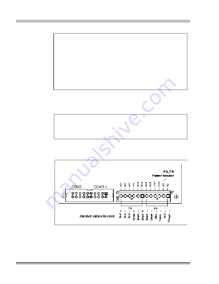
3. The power supply connector is located at P8, P9. Make certain to con-
nect the ground wires (typically black) to all ground connectors at P8,
P9 on the PC-500. Refer to Figure 2-3.
WARNING!
Accidently crossing the wires, i.e., pl5V wires into
the ground connector or the ground wires into the +5V con-
nector will damage the PC-500.
Figure 2-3 Power connector: P8, P9
Note
By removing the keys on the PC-500, it is possible to key your power
connector header to your power supply connector. To insert the power
connector without removing the keys, angle the connector at 90° and
then place it on P8, P9.
Summary of Contents for PC-500
Page 7: ...Notice to user PC 500 user s manual ...
Page 17: ...xii Contents PC 500 user s manual ...
Page 23: ...About this manual PC 500 user s manual ...
Page 25: ...Overview of Section 1 PC 500 user s manual ...
Page 35: ...2 2 Quick start PC 500 user s manual Figure 2 1 PC 500componentdiagram ...
Page 36: ...2 3 PC 500 user s manual Quick start Figure 2 2 PC 500center to centerholedimensions ...
Page 53: ...3 10 SETUP programs PC 500 user s manual ...
Page 57: ...4 4 Save and run programs PC 500 user s manual ...
Page 59: ...Overview of Section 2 PC 500 user s manual ...
Page 71: ...5 12 Serial ports PC 500 user s manual ...
Page 75: ...6 4 LPT1 parallel port PC 500 user s manual ...
Page 81: ...7 6 Console devices PC 500 user s manual ...
Page 89: ...10 2 IRQ routing and opto IRQs PC 500 user s manual Figure 10 1 Interruptroutingmatrix ...
Page 103: ...11 12 EZ I O PC 500 user s manual ...
Page 117: ...14 2 PC 104 expansion PC 500 user s manual ...
Page 119: ...15 2 SCSI PC 500 user s manual ...
Page 121: ...16 2 Ethernet PC 500 user s manual ...
Page 123: ...Overview of Section 3 PC 500 user s manual ...
Page 127: ...17 4 Watchdog timer and hardware reset PC 500 user s manual ...
Page 143: ...19 8 Transferring files remote disks PC 500 user s manual ...
Page 173: ...22 22 CPU power management PC 500 user s manual ...
Page 177: ...23 4 Troubleshooting PC 500 user s manual ...
Page 179: ...Overview of Section 4 PC 500 user s manual ...
Page 225: ...B 28 Software utilities PC 500 user s manual ...


