background image

Remarks

Action

Step

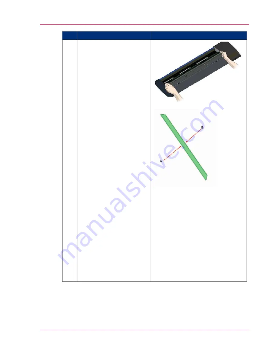
Insert a new glass plate (lower a
new glass plate into the scanner).
1. Pick up the new glass plate in
the same manner as you removed
the old one - with two hands
holding the glass on each end so
you avoid touching the glass
surface.
2. Take special care to avoid
touching the glass plate's bottom
surface which normally will not
be cleaned during maintenance.
3. Stand at the front of the scan-
ner as you hold the glass.
4. Make sure you hold the glass
for insertion with the correct
surface facing down. Note the
direction of the facetted edges
that indicate which is the bottom
surface of the glass. See the illus-
tration of the glass plate's profile
below on the right.
5. Hold the glass so that the
bottom side surface faces your
body.
6. Lower the new glass plate into
the scanner at an angle, as shown
in the glass plate's profile view
below, so that the glass's lower
edge meets the scanner's bottom
position groove.
(A= Bottom surface, B = Top
surface).
CAUTION: The glass plate is
long and thin and thus fragile.
Take care not to break it.

11

Chapter 7 - Maintenance

57

Replacing the glass plate

Summary of Contents for CS4236

Page 1: ...o Océ CS4236 User Manual Océ CS4236 Océ User manual ...

Page 2: ... Océ Technologies B V makes no representation or warranties with respect to the contents hereof and specifically disclaims any implied warranties of merchantability or fitness for any particular purpose Further Océ Technologies B V reserves the right to revise this publication and to make changes from time to time in the content hereof without obligation to notify any person of such revision or ch...

Page 3: ... Systems Incorporated Microsoft Windows Windows XP Windows Server 2003 Windows Vista 32 are either registered trademarks or trademarks of Microsoft Corporation in the United States and or other countries Products in this publication are referred to by their general trade names In most if not all cases these designations are claimed as trademarks or registered trademarks of their respective compani...

Page 4: ... the prevention of damage to your properties Note Attention and Caution The words Note Attention and Caution indicate important parts The attention getters with the corresponding icons Indicates Icon Word Additional information about the correct operation of the product or a tip Note Information to prevent damage for example to the product an original or a file Attention Information to prevent per...

Page 5: ...27 Loading Originals into the scanner 28 Chapter 6 Scan an original 33 Scan an original 34 Chapter 7 Maintenance 39 Maintenance Overview 40 Cleaning 42 Calibration Scanner Maintenance program 49 Replacing the glass plate 52 Downloading new firmware 60 Chapter 8 Océ Scanner Agent 63 Introduction 64 Installation of Océ Scanner Agent 65 Interface of Océ Scanner Agent 66 Chapter 9 Océ Scanner Maintena...

Page 6: ... 83 Problems Related to Operation of the scanner 85 Problems Related to Scanning Results 86 Problems Related to Océ Copy Easy 87 Technical Assistance 88 Chapter 11 Appendix 91 Important safety instructions 92 Regulations 94 Reader s comment sheet 96 Addresses of local Océ organisations 98 6 Contents ...

Page 7: ...Chapter 1 About this Manual o ...

Page 8: ...OM that came with your scanner or a newer version Out of date versions of Océ Scanner Agent software may not detect your scanner model Note Windows Compatibility Your scanner and drivers are tested and developed to support the most current active Microsoft Windows version OS systems Drivers and interface support in regard to specific Windows versions will follow the Microsoft Support Life cycle Po...

Page 9: ...Chapter 2 Overview of the Scanner o ...

Page 10: ... Scanner front view Scanner lid 1 Release buttons for opening the scanner lid for maintenance 2 Operator Panel 3 Insert slot for document feeding 4 Scanner bed paper feed area 5 Operators panel Operators panel Paper forward button 1 Paper ready indicator 2 Error indicator 3 Chapter 2 Overview of the Scanner 10 Overview of the scanner ...

Page 11: ...backside view Connection panel 1 Release buttons for opening the scanner lid for maintenance 2 Connection panel Connection panel USB interface connection 1 4 Diagnostic LEDS for reporting to service provider 2 Main power connection socket 3 Main power switch 4 Chapter 2 Overview of the Scanner 11 Overview of the scanner ...

Page 12: ...Chapter 2 Overview of the Scanner 12 Overview of the scanner ...

Page 13: ...Chapter 3 Installation o ...

Page 14: ...applications Caution The scanner is equipped with a three wire pin grounding type plug If you cannot insert the plug into your outlet contact your electrician to replace the plug or outlet to ensure a grounded power connection Do not try to defeat or ignore the purpose of the grounding type plug System requirements PC or supported workstation Compatible Windows operating system Enabled USB port on...

Page 15: ...r to allow the media to run out 1 Install drivers and tools on your PC 1 Insert the CD ROM into your PC Normally the setup program interface will start automatically If it does not locate the set up exe file on the CD and start it manually 2 Follow the instruction of the wizard 4 Remove the CD ROM when installation is complete 2 Shut down the PC Your PC must be powered off before connection with t...

Page 16: ...5 Open the scanner lid Press the lid release buttons The internal scan area should be wiped clean for any dust accumu lated during packaging and shipping The scan area is under the scanner lid so you have to open it The scanner lid release buttons are at the back of the lid 1 Stand at the front of the scan ner 2 Simultaneously slide the re lease buttons towards the scan ner s center with your fing...

Page 17: ...at cannot be wiped clean with a dry cloth refer to this guide s section Cleaning the scan area for instructions on thorough ly cleaning the scan area in con nection with scanner mainte nance 8 Connect the interface cable to the scanner Connect the B connector square shaped end to the USB connec tion socket on your scanner The USB connection socket is at the scanner s back 9 Connect the other end o...

Page 18: ...of the scanner power cable to the power outlet Note The scanner is equipped with a three wire pin grounding type plug If you cannot insert the plug into your outlet contact your electrician to replace the plug or outlet to ensure a grounded power connec tion Do not try to de feat or ignore the pur pose of the grounding type plug 12 Switch on the scanner Switch on the main power switch at the back ...

Page 19: ...indows System Tray This is the Océ Scanner Agent program icon 2 Left double click on the Océ Scanner Agent system program icon 3 Your scanner is installed and detected if your scanner s name appears at the top of the Océ Scanner Agent system Status tab dialog 4 If the scanner was not in stalled correctly a message will inform you that your scanner could not be detected If this is the case turn off...

Page 20: ...Chapter 3 Installation 20 Installation ...

Page 21: ...Chapter 4 Switch the scanner ON and OFF o ...

Page 22: ...rn the mains power to ON 1 Press the lower half of the switch marked 0 to turn the main power to OFF 2 Selftest procedure Remarks Action Step When you turn the mains power ON the scanner runs a short self test procedure This takes less than a minute The 3 LEDs on the panel will be lighted during the self test proce dure 1 Chapter 4 Switch the scanner ON and OFF 22 Main Power switch ...

Page 23: ... when the power LED turns green The scanner starts up in Wake mode see Sleep and wake modes on page 24 1 You can leave the main power switch permanently ON and control scanner power through its Sleep and Wake modes 2 Chapter 4 Switch the scanner ON and OFF 23 Main Power switch ...

Page 24: ...ep mode Remarks Action The scanner will go from Wake mode into Sleep mode Automatically after a set idle time see Sleep mode options below Manually when you hold the power button down for 3 seconds 1 Scanner in Sleep mode Power LED is orange 2 From Sleep mode into Wake mode Remarks Action Step The scanner will go into Wake mode from Sleep mode When you feed a document into the scanner When you pre...

Page 25: ...Remarks Action Step Scanner in Wake mode Power LED is green 2 Chapter 4 Switch the scanner ON and OFF 25 Sleep and wake modes ...

Page 26: ...Chapter 4 Switch the scanner ON and OFF 26 Sleep and wake modes ...

Page 27: ...Chapter 5 Loading an original o ...

Page 28: ...e scanner model Illustration Automatic loading 1 With automatic loading the scanner takes the original as soon as you insert it in the paper slot Automatic loading is reliable for most jobs and especially useful for batch scanning jobs Make sure the Paper handling option Auto load is set in your scanning application 2 Align the center of the document with the center arrow marking on the scanner be...

Page 29: ... bed 3 Push the original into the insertion slot until you feel it contact the rollers and the Paper Ready LED lights green 4 While holding the original in place with one hand use the other hand to press and hold down the Paper Forward button on the scanner When Paper Ready LED green press the Paper Forward button 5 The original moves into the start scan position Unloading the original after scan ...

Page 30: ... both Manual and Automatic loading Note The availability of the soft handling load option depends on your scan copy software and its level of compatibility with the scanner model Use Soft handling with Old curled or creased originals that trigger a paper jam See Trouble Shooting Paper Jam error for correcting a paper jam error Fragile originals you want passed delicately through the drive system C...

Page 31: ...ent and calculate the input size for you Set a standard size Common standard sizes are marked on the scanner bed Use these markings to deter mine which standard size matches the original and then select that size in the applica tion s input size dialog Set the size manually for irregular sizes Measure your document with the inch cm ruler on the scanner bed Enter your width measurement in the width...

Page 32: ...Chapter 5 Loading an original 32 Loading Originals into the scanner ...

Page 33: ...Chapter 6 Scan an original o ...

Page 34: ...nner software and compatible third party appli cations Running applications from the scanner panel 1 Normally you would control the scanner from your PC through your scan software user interface However your scanner also supports one touch buttons that enable you to trigger scanner compatible software from the scanner panel Configuration of your one touch buttons is controlled through Océ Scaner a...

Page 35: ...omatic loading optional for fast and effective loading Read you scan software s on line help pages for specific information on batch scanning with the applica tion Note The availability of Batch scanning options will depend on your scan copy software and its level of compatibility with the scanner model Monitoring your scanner with Océ Scanner agent 1 You installed Océ Scanner agent with the scann...

Page 36: ...2 Chapter 6 Scan an original 36 Scan an original ...

Page 37: ...an of the system s hardware bus for re establishing the interface Right click on the scanner icon select Advanced Options Rescan Hardware Bus Assign reassign applications to the scanner s one touch scan buttons or disable the one touch scan buttons altogether Open the One Touch tab to make settings Set up your scanner so it can be shared by user PC s on the network Open the Scan to Net tab to make...

Page 38: ...Chapter 6 Scan an original 38 Scan an original ...

Page 39: ...Chapter 7 Maintenance o ...

Page 40: ... the sole cause of streaks in the end result See more under the section Cleaning the scan area 2 Calibration Calibrate the scanner if your output is not optimal and cleaning above does not remedy the problem Calibration will renew the scanner s original color and BW precision Scanner Calibration is easy to perform To run you insert a Calibration Sheet and start the Scanner Maintenance program The ...

Page 41: ...nth and always right before important jobs that require a high degree of precision You must clean the following scanner parts areas The scanner bed Glass plate Upper precision rollers Lower pressure rollers Lower rubber transport rollers Note To help locate these parts on the scanner see the Overview of key maintenance points Cleaning on the next page Chapter 7 Maintenance 41 Maintenance Overview ...

Page 42: ...he scanner This step is to ensure your own personal safety and to help protect your device from potential damage Caution Do not spray apply cleaner fluids directly on the glass plate or anywhere else in the scan area Overview Key Maintenance cleaning points Overview 1 Lower rubber transport rollers black 2 Lower pressure rollers long white 3 Upper precision rollers 4 Opening lid to access scan are...

Page 43: ...he power plug Note Always disconnect pow er before cleaning the scanner This step is to ensure your own person al safety and to help protect your device from potential damage 2 Clean the scanner surface Clean your scanner s flat surface so dirt and dust are not dragged into the scan area with the origi nal 3 Chapter 7 Maintenance 43 Cleaning ...

Page 44: ... front of the scan ner 2 Simultaneously slide the re lease buttons towards the scan ner s center with your fingers until you feel them unlock 3 Use your other fingers to grip the edge of the lid 5 Open the scanner lid Pull the lid back Retain pressure on the lid release buttons and your grip on the lid edge as you pull the lid back wards towards your body Open the scanner lid all the way back 6 Ch...

Page 45: ...Spray apply a mild streak free glass cleaner onto a lint free cloth 2 Gently wipe the glass clean 3 Dry the glass completely using the other clean dry lint free cloth 4 Make sure that fluids to not get under the glass and that you leave the area dry CAUTION Do not spray apply cleaner fluids directly on the glass plate or anywhere else in the scan area 7 Chapter 7 Maintenance 45 Cleaning ...

Page 46: ... with the origi nal s ink side and thus may re quire extra care when cleaning 1 Spray apply a mild streak free glass cleaner onto a lint free cloth 2 Gently wipe the rollers sur face 3 Use the cloth to turn the rollers so you wipe all sides 4 Dry the rollers completely us ing another clean dry lint free cloth 5 Make sure that you leave the area dry CAUTION Do not spray apply cleaner fluids directl...

Page 47: ...a mild streak free glass cleaner onto a lint free cloth 2 Gently wipe the white roller s surface 3 Use the cloth to turn the rollers so you wipe all sides 4 Dry the rollers completely us ing another clean dry lint free cloth 5 Make sure that you leave the area dry CAUTION Do not spray apply cleaner fluids directly to the rollers or anywhere else in the scan area 9 Chapter 7 Maintenance 47 Cleaning...

Page 48: ...the axels so you only need to turn one to turn them all 4 Dry the rollers completely us ing another clean dry lint free cloth 5 Make sure that you leave the area dry CAUTION Do not spray apply cleaner fluids directly to the rollers or anywhere else in the scan area 10 Close the lid 1 Close the scanner lid all the way down until you here the lid latches click 2 Gently try to pull open the lid to en...

Page 49: ... the wizard take over Note Be sure to clean the scanner and scan area before calibrating Procedure Remarks Action Turn the scanner power ON If the main power is OFF press the main power switch at the back of the scanner to the ON position If the scanner is in Sleep mode press any button to set it in Wake mode 1 The scanner is ready for calibra tion when the power LED lights green 2 Chapter 7 Maint...

Page 50: ...the cali bration steps Click the Next button in the welcome dialog to proceed 4 Insert the calibration sheet During the process the wizard will ask you to insert the Calibra tion Sheet that came with your scanner The sheet s printed side must be inserted face up Align the sheet s midpoint arrow with the scanner s midpoint ar row and feed the sheet into the scanner Click the wizard s Next button to...

Page 51: ...number of times as the program processes data Let the program complete all calibration steps 6 Finished The wizard will tell you when the process is finished 1 Remove the Scanner Calibra tion Sheet from the scanner 2 Return the Scanner Calibra tion Sheet to its protective cover and then place it in the storage folder Store the folder in a dry place and out of direct light 7 Chapter 7 Maintenance 5...

Page 52: ...lass plate is held and locked in place with 4 small white colored latches Each latch can be released from the glass plate by pressing down on its corresponding latch release button Each latch release button is placed in a square hole just under the latch it releases Caution Disconnect the power plug This step is to ensure your own personal safety and to help protect your device from potential dama...

Page 53: ...damage 2 Open the scanner lid Press the lid release buttons The glass plate is in the scan area under the scanner lid You need to open the lid to re place it 1 The scanner lid release but tons are at the back of the lid 2 Stand at the front of the scan ner 3 Simultaneously slide the re lease buttons towards the scan ner s center with your fingers until you feel them unlock Use your other fingers t...

Page 54: ...t the scanner s right side 1 Detaching the first right most latch requires a sharp flat tool such as a pen or a small screwdriver Note Detaching the remaining 3 latches will not require use of a tool 2 Locate the arrow label at the scanner s right side 3 Position the tool just under the glass plate edge where the arrow label indicates At the same time press down on the latch release button in the ...

Page 55: ...6 Detaching the glass plate free the 3rd latch 1 Press down on the latch re lease button in the 3rd square hole from the right 2 The 3rd latch will release its grip and the glass will pop up over the latch 3 Let go of the latch release button 7 Detaching the glass plate free the 4th latch 1 Press down on the latch re lease button in the 4th square hole from the right leftmost hole 2 The 4th latch ...

Page 56: ...t get your thumbs under the glass use the sharp flat tool from step 5 to tip the glass high enough to get a thumb underneath 3 Tip the glass back and up so its two ends are free 9 Detaching the glass plate Lift the glass plate edge out of the scanner 1 Move your hands one at a time to each end of the glass 2 Apply light pressure with each hand as you lift the glass out of the scanner CAUTION The g...

Page 57: ...u hold the glass for insertion with the correct surface facing down Note the direction of the facetted edges that indicate which is the bottom surface of the glass See the illus tration of the glass plate s profile below on the right 5 Hold the glass so that the bottom side surface faces your body 6 Lower the new glass plate into the scanner at an angle as shown in the glass plate s profile view b...

Page 58: ...glass plate rests in the scanner lid between the 2 grooves top bottom position grooves 12 Lock the new glass plate in place The glass needs to be locked in place with the four latches At this point the latches are under the glass plate and they need to be brought above so they grip the glass plate s edge 1 Start at the right side 2 Press down on the first right most latch release button 3 With you...

Page 59: ...hat fluids to not get under the glass and that you leave the area dry CAUTION Do not spray apply cleaner fluids directly on the glass plate or anywhere else in the scan area 14 Glass plate replaced successfully 1 Close the scanner lid all the way down until you here the lid latches click Gently try to pull open the lid to ensure it is locked in the closed position 2 Plug in the scanner and turn th...

Page 60: ...are made to the scanner though its firmware 2 An error is discovered in the firmware version you have in the scanner and Océ recom mends installation of new firmware in which the error is corrected NOTE Your manufacture s website specifies improvements with every new firmware release How to identify the firmware version running in the scanner 1 1 Start Océ Scanner Agent Left click on the system tr...

Page 61: ...w firmware is installed by opening the firmware exe file The firmware exe file must first reside on your machine Select the Save target or Save Link option if downloading from the web Chapter 7 Maintenance 61 Downloading new firmware ...

Page 62: ...Chapter 7 Maintenance 62 Downloading new firmware ...

Page 63: ...Chapter 8 Océ Scanner Agent o ...

Page 64: ...main features available from this application Gain visual indication that the scanner is connected to the PC View the scanner s status called the Scanner Mode by moving the mouse over the scanner icon on the system tray Status messages include remaining warm up time interface connection errors and an indication that the scanner is ready for scanning View useful Error messages related to the curren...

Page 65: ...tall Océ Scanner Agent 1 Insert the CD ROM in your CD driver The setup program is launched automatically 2 Follow the instructions of the setup wizard 3 At the end of the installation the wizard asks if you want to run Océ Scanner Agent at start up Click Yes if you want the application to be started automatically each time you boot your PC Note This is recommended when you define times to power on...

Page 66: ...of Océ Scanner Agent Start of Océ Scanner Agent There are two ways to start the program From the Windows Start menu select Programs Océ Scanner Agent Chapter 8 Océ Scanner Agent 66 Interface of Océ Scanner Agent ...

Page 67: ...s tab displays useful messages about what the scanner is currently doing and displays error messages when relevant Scanner mode What the scanner is doing at any given moment Here is a list of the different scanner modes Chapter 8 Océ Scanner Agent 67 Interface of Océ Scanner Agent ...

Page 68: ...w the error message Not Ready Error detected The scanner test mode is used during technical service Test Mode The scanner is performing test operations to ensure optimal performance light profile corrections stitching etc Continuous self test mode The scanner is performing calibration of the cameras Calibrating The scanner is adjusting its cameras Adjusting The scanner is in standby mode when the ...

Page 69: ... full maintenance process adjustment stitching and calibration Contact your Océ service technician if the problem persists Stitching of Cam era X Y A B or B C or C D failed Note If you encounter another error message try to shut down and reboot your system Note If the problem persists contact your technical support Make sure you have the Error message text and information from the Info tab on hand...

Page 70: ...nufacturer Firmware build number Firmware revision User The amount of time your scan ner has been turned on Scanner uptime User The time lapsed since the scan ner last performed auto adjust ment Time since adjustment Support Internal to manufacturer The date the firmware was compiled Firmware timestamp User Support The date time the current firmware was downloaded to the PC Firmware download time ...

Page 71: ...tal length scanned Total roller movement Used to monitor and plan the scanner maintenance Lamp light on Last calibration timestamp Lamp light on It is advised to replace the lamp every 4000 hours of use Note Make sure to use the timer settings to save the lamp usage when the scanner is idle see Last calibration timestamp It is recommended that you clean align and calibrate your scanner at least 7 ...

Page 72: ...rature is essential when making high quality scanning through sensitive CCD s Your scanner needs to warm up before it can start scanning optimally The Timer Settings tab lets you program the scanner to automatically power on and warm up times most convenient for you so it stands ready when you need it You do not have to waste valuable time waiting for your system to reach optimal conditions Set yo...

Page 73: ...tral power switch has been turned OFF manually and its clock needs to be reset 7 Quick Menu The Océ Scanner Agent quick menu offers an easy way to initiate common scanning ac tions and a direct link to other Océ applications To access the quick menu right click the Océ Scanner Agent icon on the system tray see The following menu is displayed Advanced Options This submenu contains options related t...

Page 74: ...ard which will guide you through the camera alignment and calibration procedure Note These two options above are available if the Océ Scan and Scanner maintenance have been previously installed on your computer Restore Océ Scanner Agent Use this option to display the Océ Scanner Agent main interface About Océ Scanner Agent This option displays information about the version of Océ Scanner Agent Exi...

Page 75: ...Chapter 9 Océ Scanner Maintenance o ...

Page 76: ...rs are installed with Océ Scanner Agent and help you set up correctly your system Install Océ Scanner Maintenance 1 Océ Scanner Maintenance is part of the installtion wizard Start Océ Scanner Maintenance 1 Power on the scanner 2 From the Windows Start menu select Programs and Scanner Maintenance 3 In the Scanner Maintenance menu select Scanner Maintenance The application detects the scanner and st...

Page 77: ...do is follow the instructions on the screen For more details about the procedure please refer to the Scanner Maintenance leaflets provided with the software OcéScanner Maintenance is performed in three consecutive steps Cleaning of the scan area Camera alignment Calibration Basic calibration and Colour calibration Cleaning To clean the scan area use the special cleaning cloth provided with the SMK...

Page 78: ... those in another production batch Colour matching and calibration are optimal when using your IT8 Calibration sheet with an IT8 calibration sheet reference data file corresponding to the sheet s production batch The Scanner Maintenance CD comes with a number of these files that are installed with the maintenance program The IT8 sheet batch ID is contained in the bar code on your maintenance sheet...

Page 79: ...ction requires that you are connected to the internet Use Standard IT8 file The standard IT8 file IT8data IT8 comes with the maintenance program and is installed on your system The file can substitute for the right IT8 calibration sheet reference data file but is however far from optimal Browse This button lets you search for the corresponding IT8 calibration reference data file on your file syste...

Page 80: ...Chapter 9 Océ Scanner Maintenance 80 Océ Scanner Maintenance program ...

Page 81: ...Chapter 10 Trouble Shooting o ...

Page 82: ...e and cause of the error may be reported immediately through a message on your screen If not open Océ Scanner Agent double left click the scanner icon on your system tray and select the Status tab to view additional information about the error 2 The information on your screen may include instructions and actions to remedy the error Follow the instructions on your screen 3 Look for a description of...

Page 83: ... plug in the scanner power and turn on the scanner main power switch Unknown device is found message If you connected and tried to install the scanner before installing Océ Scanner Agent the unknown device found message will appear If you ignored this and continued to step through the dialogs from there the scanner will be entered on the system as a new device without functional drivers If this is...

Page 84: ... the scanner Shut down the scanner and PC unplug the connec tions and restart the installation from step 1 as described above Loose interface connection on both end unplug and then firmly plug in the interface cable System needs rebooting shut down the scanner and PC unplug the connections Then plug in the interface connec tions turn on the PC and when Windows is loaded turn on the scanner Océ Sca...

Page 85: ...ay include instructions and actions to remedy the error Follow the instructions on your screen Look for a description of the error in this users guide Follow the instructions provided In some cases you may need technical assistance You should contact your service provider if one or more of the following cases is true a the error can not be remedied through the action sug gested on your PC screen b...

Page 86: ...ider Stitching problems Image sections misaligned at points between the sensors overlap ping pixels This is often caused by an unclean glass plate Even a single spec of dirt in the wrong spot on the glass plate can apply a streak along your entire scan To remedy Clean your glass plate and rollers as described in this users s guide If the problem persists after cleaning calibrate the scanner with t...

Page 87: ...r Move the cursor over the copy button Check the information Examples Media to small The Quality still not OK Step 1 Original type selection is not correct Select a different original type Example Mixed Originals Step2 Selected media not correct Example Photo on Draft paper is not correct Select an other media type Step 3 Original and Media is correct Do a Calibration Closed Loop Calibration Selec...

Page 88: ...able for the Océ Helpdesk Serial number of the printer Serial number of the scanner Used driver or application A good problem description Technical assistance Remarks Action Step the error can not be remedied through the action suggested on your PC screen the error and its remedy is not described in this users guide the system fails to report the error on your screen 1 Chapter 10 Trouble Shooting ...

Page 89: ...abel on the back of the scanner 2 Write down your Firmware version 3 See the section How to identi fy the firmware version running in the scanner 4 There are 4 diagnostic LEDs at the scanner back Their current lighting status may tell the technician something about the error Write down the lighting and color pattern of the diagnostic LEDs 2 Chapter 10 Trouble Shooting 89 Technical Assistance ...

Page 90: ...Chapter 10 Trouble Shooting 90 Technical Assistance ...

Page 91: ...Chapter 11 Appendix o ...

Page 92: ...d with the scanner make sure that the total ampere ratings of the products plugged into the extension cord does not exceed the extension card ampere rating Make sure that the total rating of all products plugged into the wall outlet does not exceed 15 amperes H Slots or openings in the cabinet at the back or bottom are provided for ventilation This ensures reliable operation of the product and pro...

Page 93: ...red by the instructions in this manual Improper adjustment of controls other than those mentioned in this manual may result in per manent damage and will at best require extensive work by a qualified technician to restore this product to its normal operation If the scanner has been dropped or the cabinet has been damaged If the scanner exhibits a distinct change in performance indicating a need fo...

Page 94: ...r television reception which can be determined by turning the equipment off and on the user is encouraged to try to correct the interference by one or more of the following measures Reorient or relocate the receiving antenna Increase the separation between the equipment and receiver Connect the equipment into an outlet on a circuit different from that to which the receiver is connected Consult the...

Page 95: ...below the limit requirement in SJ T11363 2006 X Indicates that this toxic or hazardous substance contained in at least one of the ho mogeneous materials used for this part is above the limit requirement in SJ T11363 2006 Enterprises may further provide in this box technical explanation for marking X based on their actual conditions Chapter 11 Appendix 95 Regulations ...

Page 96: ...y and arrangement page layout chapter order etc O Yes O No Could you find the information you were looking for O Always O Most of the times O Sometimes O Not at all What did you use to find the required information O Table of contents O Index Are you satisfied with this manual O Yes O No Thank you for evaluating this manual If you have other comments or concerns please explain or suggest improveme...

Page 97: ...Company Phone Address City Country Please return this sheet to Océ Technologies B V For the attention of ITC User Documentation P O Box 101 5900 MA Venlo The Netherlands Send your comments by E mail to itc userdoc oce com For the addresses of local Océ organisations see http www oce com Chapter 11 Appendix 97 Reader s comment sheet ...

Page 98: ... http www oce com cn Océ Canada Inc 4711 Yonge Street Suite 1100 Toronto Ontario M2N 6K8 Canada http www oce ca Océ Danmark a s Vallensbækvej 45 2605 Brøndby Denmark http www oce dk Océ Czech Republic ltd Hanusova 18 140 21 Praha 4 Czech Republic http www oce cz Océ France S A 32 Avenue du Pavé Neuf 93161 Noisy le grand Cedex France http www oce fr Océ Finland OY Valkjärventie 7 D PL 3 02130 Espoo...

Page 99: ...y Océ Belgium S A Rue Astrid 2 A 1143 Luxembourg Belair http www oce lu Océ Norge A S Postboks 4434 Nydalen Gjerdrums vei 8 0403 Oslo Norway http www oce no Océ Mexico S A de C V Prolongación Reforma 1236 4to Piso Col Santa Fé Del Cuajimalpa C P 05348 México D F México http www oceusa com Océ Lima Mayer S A Av José Gomes Ferreira 11 Piso 2 Mi raflores 1497 139 Algés Portugal http www oce pt Océ Po...

Page 100: ...dom http www oce co uk Océ Nederland B V P O Box 800 5201 AV s Hertogenbosch The Netherlands http www oce nl Océ North America Inc 5450 North Cumberland Avenue Chicago IL 60656 USA http www oceusa com Note The web site http www oce com gives the current addresses of the local Océ organisa tions and distributors Note The addresses of local Océ organisations for information about the Wide Format Pri...

Page 101: ...4 Clean 40 Cleaning 42 Connection panel 10 D Documentation 8 Download 60 E Error 66 82 83 error 86 Error indicator 85 F Firmware 60 G Glass plate 40 52 I image 86 Information 66 installation 76 Installation scanner 14 IT8 77 L Led 85 Load original 28 M Main Power switch 22 Maintenance 42 49 Manual loading 28 N Note 4 101 Index ...

Page 102: ...l 34 Scanner Agent 66 Scanner backside view 10 Scanner front view 10 Scanner installation 83 scanner maintenance 76 Selftest procedure 22 Set input size 28 Sleep mode 24 Status 66 Switch the scanner ON and OFF 22 T Technical Assistance 88 Trouble shooting 82 W Wake mode 24 102 Index ...

Reviews: