background image

Operating & Maintaining the Connex500/350 3-D Printer

7–2


DOC-13000 Rev. E

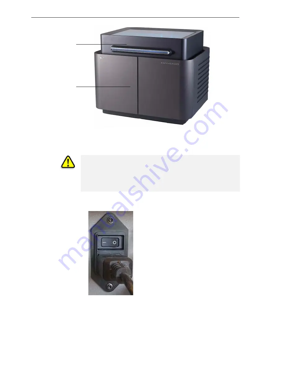
Figure 7-1: The Connex500 3-D Printer 

Starting the Connex Printer

1. Turn


on


the


main


power


switch,


located


at


the


back


of


the


Connex


printer.

Figure 7-2: Main power cable and switch

The


main


power


switch


turns


on


the


Connex


printer,


which


includes


the


built

in


Connex


computer.


Printer cover

Printing-materials &

storage compartment

CAUTION

!

Do not attempt to operate the Connex printer before being trained by 
an Objet customer-support representative.

Observe all safety warnings and follow the safety guidelines described 
in chapter 2.

All manuals and user guides at all-guides.com

Summary of Contents for Connex500

Page 1: ...Maintaining the Connex Printer 18 Routine Maintenance Schedule 18 Cleaning the Print Heads 19 Pattern Test 21 Improving Print Quality 22 Cleaning and Replacing the Wiper 23 Replacing the Roller Scrap...

Page 2: ...Main power cable and switch The main power switch turns on the Connex printer which includes the built in Connex computer Printer cover Printing materials storage compartment CAUTION Do not attempt to...

Page 3: ...ter for the application to open This key should be installed during printer installation If the application does not open and a HASP message appears contact your dealer or Objet Customer Support Print...

Page 4: ...Load model and support cartridges into their respective compartments the model cartridge on the right and the support cartridge on the left Note that the cartridges only fit into their correct compar...

Page 5: ...ges from Idle to Pre print as the printer s components prepare themselves for production The print block is heated The UV lamps are powered and they warm up When printing begins Job Manager sends seve...

Page 6: ...tatus indicators by switching the printer interface display To do this click the display toggle button in the printer interface screen Figure 7 4 Connex printer indicators Block temp in front of suppo...

Page 7: ...um level in the system is within the acceptable range Red not suitable for printing or indicates a warning For example in figure 7 4 Waste The weight of the waste container is grams more than allowed...

Page 8: ...being performed is shown in the current activity field Current job printing information is displayed The printing progress bar is displayed The Stop and Pause buttons are enabled When the weight of a...

Page 9: ...face after interrupted printing Figure 7 7 Continue from Slice confirmation dialog box in server Job Manager interface 5 If for any reason the correct number does not appear in the dialog box enter th...

Page 10: ...d from the Options menu 2 In the opening screen click Next 3 If the printer cover is not closed a screen appears instructing you to close the cover Confirm that it is closed and click Next You can sto...

Page 11: ...rtridges and the printer will be loaded with two cartridges containing the same model material the Connex printer flushes the entire system and prepares for printing in Single Material mode see below...

Page 12: ...al This mode is required to produce build trays with the High Quality setting and to produce trays with the High Speed setting using only one model material Digital Material mode Each of the model mat...

Page 13: ...ause it can potentially save 25 to 75 percent of the material used to flush out the old material compared to the High Performance cycle Note however that there may be times when the shade color of the...

Page 14: ...After identifying the new cartridge s the Connex printer begins filling the print heads with the new model material Figure 7 15 Material replacement filling heads with new material Once you start thi...

Page 15: ...e interface see figures 7 3 7 4 and 7 5 on pages 3 6 and 8 If after printing a job you know that the printer will not be used for 10 hours or more you can immediately turn off the heating of the print...

Page 16: ...thorough procedure Up to 10 days The wizard empties the print block of model and support material to prevent leaks This takes about 10 minutes More than 10 days The wizard empties the print block then...

Page 17: ...n the final wizard screen appears close the printer control application and shut down the built in computer Figure 7 18 Final Shutdown Wizard screen 6 After the printer computer shuts down turn off th...

Page 18: ...and Replacing the Wiper on page 7 23 Weekly Restart the Connex printer computer and the server computer Weekly Clean the roller waste collector See Cleaning the Roller Waste Collector and Inspecting t...

Page 19: ...big printing job To clean the print heads 1 Prepare isopropanol IPA isopropyl alcohol or ethanol ethyl alcohol disposable cleaning gloves an Objet supplied cleaning cloth or equivalent a mirror 2 Sta...

Page 20: ...ure 7 21 Use the mirror to make sure that you have removed all of the residue material Figure 7 21 Cleaning the heads 10 When you have finished cleaning select the confirmation check box in the wizard...

Page 21: ...nt heads Make sure therefore that you perform this test weekly and whenever you suspect a printing problem To perform the pattern test 1 Make sure that the build tray is empty 2 Prepare a sheet of pin...

Page 22: ...oor use the following procedure to improve print quality If the results of the last pattern test are poor 1 From the Options menu select Execute Purge Sequence or press F4 2 In the confirmation dialog...

Page 23: ...the wiper is damaged or worn replace it To inspect and clean the wiper 1 Prepare isopropanol IPA isopropyl alcohol or ethanol ethyl alcohol disposable cleaning gloves an Objet supplied cleaning cloth...

Page 24: ...h remove any material remaining on the wiper and the surrounding area 9 Inspect the wiper If the wiper is scratched torn or worn or if you cannot clean it completely replace it a Grasp it and pull it...

Page 25: ...waste material scraped from the roller Suction removes this waste to the printer s waste container This assembly should be cleaned weekly to prevent a blockage in the tubes leading to the waste contai...

Page 26: ...V lamp 4 Loosen the two screws securing the suction tube on the print block Figure 7 31 Lifting the suction tube 5 Lift the suction tube to secure it in a raised position 6 Remove the two screws secur...

Page 27: ...loth with isopropanol 3 Use the cloth to wet the bottom of the roller 4 Turn the roller slowly with your hand As the blade scrapes the roller make sure the isopropanol is spread evenly over the entire...

Page 28: ...nife You should replace the roller scraper blade after 1 000 hours of printing if it does not effectively keep the roller clean To replace the roller scraper 1 Prepare a new roller scraper knife Kit 0...

Page 29: ...y Figure 7 37 Removing the roller scraper screws Figure 7 38 Removing the old roller scraper blade 5 Remove the scraper blade and discard it 6 Place the new scraper blade onto the pins in the holder a...

Page 30: ...ds if model quality is not acceptable even after cleaning the orifice plate on the bottom of the print block see Cleaning the Print Heads on page 7 19 The head alignment procedure takes about 20 minut...

Page 31: ...ray 6 Make sure that the transparency sheet is lying flat and tape it to the tray 7 In the wizard screen select the check box to confirm that the transparency sheet is on the build tray and click Next...

Page 32: ...glass or loupe to inspect pairs of consecutive rows printed on the transparency to see where the vertical lines align Figure 7 44 Comparing rows of alignment lines Note It does not matter which pair...

Page 33: ...ts the head alignment accordingly 12 Click Next to display the next head alignment screen and again select the number representing the most closely aligned vertical lines on the transparency for that...

Page 34: ...s by running the Head Optimization wizard During the optimization process 32 samples are printed on the build tray After carefully weighing each of them you enter the weight in the wizard s data entry...

Page 35: ...ext to begin The Wizard Conditions screen appears 4 Read the conditions select I Agree and click Next 5 Close the printer cover and confirm this in the wizard screen 6 In the following screen make sur...

Page 36: ...e 7 51 Cleaning the print heads Use the mirror to make sure that you have removed all of the residue material 12 When the print heads are clean select the confirmation check box in the wizard screen a...

Page 37: ...er inspecting each of the printed samples Figure 7 53 Weight Test Data Entry screen a Enter the number of faulty missing nozzles Faulty nozzles are seen in Weight Test samples as a missing row of prin...

Page 38: ...y indicator moves to the next position d Repeat these steps for all 32 samples To change an entry click Edit Data enter the correct data and click Save 17 When you have entered the all of the data in...

Page 39: ...heads found 18 Choose Replace defective head s if you are prepared to replace the print heads now or Choose Abort wizard if you want to replace the print heads at another time If you are replacing th...

Page 40: ...wing phases A Identifying the head s needing replacement This is normally done by the Head Optimization wizard Otherwise evidence of physical damage to the head surface or a malfunction message indica...

Page 41: ...heads and click Next Preparing the print block 6 Select the print head s needing replacement and click Next Figure 7 58 Head selection screen The Connex printer heats and empties the print block and p...

Page 42: ...ce the defective head when this screen appears Removing the Defective Head 9 On the print block release the upper and lower screws that secure the print head in the block If necessary you may use a sc...

Page 43: ...out of its socket so that the head is free A and remove it from the bottom of the print block B Figure 7 64 Releasing the print head driver card to remove the head 13 Make sure that along with the he...

Page 44: ...14 Inspect the replacement head and make sure that the O ring seals are in place see figure 7 65 15 Gently insert the replacement head into the vacant slot in the print block and push the print head d...

Page 45: ...in place 18 Tighten the upper and lower screws that secure the print head in the print block see figure 7 61 on page 42 Note Hand tighten these screws Do not use a screwdriver 19 With your fingers mak...

Page 46: ...oblems the Head Optimization procedure begins see Calibrating Print Heads on page 7 34 If a vacuum leakage is detected or if there are other problems the wizard alerts you and instructs you how to con...

Page 47: ...inter software does not sense the replaced head the following warning screen appears Figure 7 73 Incorrect installation screen If this happens a Open the print head compartment see figure 7 63 on page...

Page 48: ...rd screen select the check box to confirm that you have installed another print head and click Next c Contact your authorized Objet Customer Support center about the unformatted head If the vacuum tes...

Page 49: ...djusted the wizard continues to the next phase the final wizard screen indicates that the lamp s radiation for the printing mode is unacceptable To test and calibrate UV lamp radiation 1 Start the UV...

Page 50: ...is shows the current condition of the lamps after the wizard has calibrated them Figure 7 77 Results and current condition of the UV lamps 3 Cover the UV sensor and confirm this in the next screen 4 I...

Page 51: ...the Load Cell Calibration wizard To calibrate load cells 1 Start the Load Cell Calibration wizard From the Options menu of the printer interface see figure 7 26 on page 23 select Wizards Load Cell Cal...

Page 52: ...Click Done in the final wizard screen Figure 7 82 Final wizard screen Replacing the Odor Filter The Connex500 350 printer has an activated carbon filter for removing odors from printing materials The...

Page 53: ...offline mode 2 Start the UV Lamp Replacement wizard From the Options menu of the printer interface see figure 7 26 on page 23 select Wizards UV Lamp Replacement 3 Make sure that the build tray is empt...

Page 54: ...cting the UV lamp Note Do not disconnect the power connection to the cooling fans 6 Loosen the screw securing the UV lamp cover A and pull the cover up B then out C Figure 7 87 Removing the UV lamp co...

Page 55: ...as long as the black paint has not faded 9 Discard the old reflector and lamp 10 Insert the new UV lamp reflector unit into the housing next to the print block Figure 7 89 Print block and UV lamp ass...

Page 56: ...lamp s and that the black strip is attached then click Next Figure 7 92 UV installation confirmation screen The wizard operates the lamps and checks if their power is within the acceptable range for e...

Page 57: ...ects the operation of the printer you can only open the Built in Tests interface when the Connex system is not printing The test suite features The organization of printing related tasks in categories...

Page 58: ...tests and the results are displayed Figure 7 96 Built In Tests screen Test List Test Name This column lists all of the tests together with selection check boxes Click the check boxes to select the tes...

Page 59: ...est failed Unknown results The test has not been run yet All Click to select all of the tests in the list None Click to de select all of the tests in the list Unknown Click to select all test that hav...

Page 60: ...y number of reports for the tests you run the name of the file saved is BITReport date time htm By default these files are saved in the Connex installation folder but you can save it in any other fold...

Page 61: ...ure of RAM memory allocation in the Eden computer Block Filling Analyzes the thermistor readings when the block is full and when it is empty Faulty thermistor Interlock Tests the interlock in the prin...

Page 62: ...iner You can monitor the weight of the waste container in the Maintenance screen of the printer interface You can also visually inspect the level of waste in the container To access it see page 7 63 T...

Page 63: ...inter 3 Place the new waste container next to the full container 4 Unscrew the cap securing the waste drain tube and connect it to the new container 5 Close the full container with a sealing cap 6 Clo...

Page 64: ...ble Cleaning Agents mild soap solution common household cleaners and window cleaners common commercial and industrial detergents 5 solution in water alcohol ethanol isopropanol 10 to 40 solution in wa...

Page 65: ...DOC 13000 Rev E 8 1 Handling Printed Models Removing Models After Printing 2 Removing the Support Material 2 Storing Models 3 All manuals and user guides at all guides com...

Page 66: ...g the Support Material After printed models have cooled the support material must be removed This can be done by different methods depending on the size of the model how delicate it is the amount and...

Page 67: ...ally between half an hour and several hours In any case you should remove as much support material as possible before the caustic soda treatment and rinse the model thoroughly with a water jet afterwa...

Page 68: ...Handling Printed Models 8 4 DOC 13000 Rev E All manuals and user guides at all guides com...

Reviews: