


Hardware Preparation and Installation
MC92602 Reduced Interface SerDes Design Verification Board User’s Guide, Rev. 3
2-2
Freescale Semiconductor
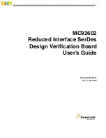
Figure 2-1. Top Side Part Location Diagram
2.3.2
Setting the Voltage Regulators
The +5.0-V supply is used to power 3 onboard voltage regulators, VR33, VR18, and VR15. These
regulators ge3.3, +1.8, and +1.5/1.8 V (V
DDQ
), respectively. The +3.3-V supply provides power
to the oscillator and clock buffer chips. This supply can be varied over the range +3.3 V ± 0.3 V using the
R12V potentiometer.
The +1.8-V supply is used to power the MC92602 core logic, transceivers, and on-chip phase-locked loop
(PLL). This regulator can be adjusted over the range +1.8 V ± 0.15 V using R22V.
The +1.5-V (HSTL) V
DDQ
supply powers the MC92602 control signal, parallel input, and output interface
circuitry. This voltage level is determined by the desired logic interface. The +1.5-V supply can be adjusted
using a R22V1 potentiometer from +1.5 V + 0.45 V/– 0.15 V. If desired, the +1.5-V regulator can be
adjusted to match the +1.8-V range for evaluation in those systems that do not contain a se1.5-V
supply.
Serial
Differential
SMA
Connectors
+5-V Power
Connectors
Voltage
Horizontal
50-
Ω
Test Traces
Regulators
Crystal
Oscillator
Clock
Buffers
DIP
Switch
MC92602
+1.5- and +1.8-V
Power
Connectors
50-
Ω
Vertical
Test Traces
2
×
20
Connectors
2
×
10
Connectors
2
×
8
Connector
+3.3-V Power
Connection
2
×
10
Connectors
2
×
8
Connector
HSTL
Reference
Test Point
NOTE:
Freescale has begun the transition of marking Printed Circuit Boards (PCBs) with the Freescale
Semiconductor signature/logo. PCBs may have either Motorola or Freescale markings during the
transition period. These changes will have no impact on form, fit, or function of the current product.
Summary of Contents for MC92602
Page 2: ......
Page 47: ...BackCover...