


DSP LASER AP with MCS
Start of Test phase
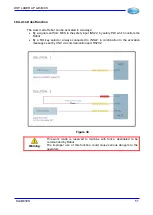
Once verified that the wiring is correct, switch the system off and then on.
Execute the following procedure:
•
Verify that the Leds relevant to Emergency (OUTG6) and to Rear Guard (OUTG1) are
ON and the Led Request Sheet Edge (OUTG2) is OFF.
•
Press the buttons Reset Emergency and Reset Rear Guard.
•
Verify that now the Leds relevant to Emergency (OUTG6) and to Rear Guard
(OUTG1) are OFF and the Led Request Sheet Edge is blinking.
•
By means of up and down keys, scroll on display until reaching the page relevant to
errors 1, 2 and 3:
E1:x E2:x E3:x
E1:x E2:x E3:x
•
Verify that both E1s are to 0:
E1:0 E2:x E3:x
E1:0 E2:x E3:x
•
Now, activate, one by one, the disabled necessary functions (Monitor, Locking,
Auxiliary Relay Emergency, etc.) through the programming parameters and execute a
test on the wiring respecting the above modalities.
•
Once the additional functions have been added and the wiring has been tested,
configure the safety outputs depending on the configurations of the press solenoid
valves.
•
If errors E1 are not both to 0, verify the type of signalled error (Chapter 14.1,
Alarms/errors and possible solution of the problems) and follow the instructions to
remove it.
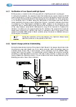
Verification of Encoders 1 and 2
Once the outputs are configured, the equipment is switched on and the emergency is reset,
pressing the Upstroke Pedal the machine should cover a length in upstroke.
Verify that the displayed position of the two Encoders match and are positive:
Y1=
mm
xxxx.x
Y2=
mm
xxxx.x
If the positions are negative or one differs from the other, verify and possibly invert the
connection of the channels A and B of one of the two encoders.
Information
:
When the press opens, the position of the two encoders must increase,
when it closes the position must decrease.
70
DLAM01EN
Summary of Contents for DSP LASER AP
Page 2: ......
Page 4: ......
Page 50: ...DSP LASER AP with MCS Figure 34 44 DLAM01EN...


