


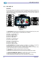


DSP LASER AP with MCS
Leave, around the module, the space necessary for an easy insertion and extraction of the
side connectors.
The choice of the module position inside the electrical panel shall even allow an easy view
of the display and an easy access to the keys under it.
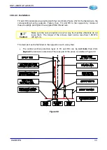
10.3.1.2. Installation
Fasten MCS module to the electric panel in stable way by means of four screws of proper
size, for example TC M5, with length in function of the shape of the electric panel.
It is mandatory to use, for the module fastening, the four holes present on the container of
the module itself.
It is strictly forbidden to drill other holes on the module container.
If you wish to execute a fastening with different dimensions, but mechanically equivalent,
realize the mechanical detail for the adaptation with the same drilling of the module and,
then, fasten the module to the adaptation mechanical detail and then fasten this to the
panel.
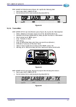
10.3.2. DSP LASER AP
Special care shall be paid to the mechanical installation, because the detection area defines
the limits of intervention of DSP LASER for the protection of the operator.
The mechanical supports must, however, be equipped with setup devices to adjust this
detection area in accurate way with respect to the tip of the upper tool of the machine.
TX and RX containers are equal: RX and TX can be, however, immediately acknowledged
by the plates applied to the relevant containers and by the front side.
The detection area must be placed under the upper tool. The manufacturer of the press has
to install the device properly on the machine, while the users has to adjust the device
properly according to the indications of the manufacturer and depending on the different
used tools.
Warning
:
The transmitter must mandatorily be installed on the left side of the press,
looking at the press from the front side. The receiver, as consequence,
must be installed on the right side of the press. The arrow indicating the
direction of the part insertion, present on the front sides of TX and RX,
must always point the back of the press.
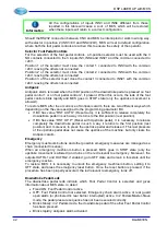
10.3.2.1. Preparation
TX and RX devices must be fastened to the upper table of the press by means of moving
supports which allows the operator of the press executing, as final movement, a sliding in
longitudinal direction along the vertical axis or a rotation.
This movement is allowed in order to execute the replacement of the upper tool. This
movement does not directly create a danger, but generates a condition equivalent to that of
laser obstructed. Then, it must be executed with care, respecting the rules and, above all, it
must not be prolonged.
Moreover a sliding in longitudinal direction is allowed along the vertical axis of calibration,
made to adapt the protection area to a tool of different size.
The moving supports must be equipped with adjustments, then not accessible to the user if
not by means of tools, to allow the following adjustments:
1. Parallelism of TX, above all because source of the laser emission, and RX with the
lower edge of the upper tool.
2. Misalignment of TX and RX with respect of the bend axis.
30
DLAM01EN
Summary of Contents for DSP LASER AP
Page 2: ......
Page 4: ......
Page 50: ...DSP LASER AP with MCS Figure 34 44 DLAM01EN...


