


DSP LASER AP with MCS
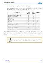
Information
:
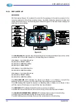
This last type of configuration is specially suitable if you wish to use
these outputs to command the power supply and/or the enabling of the
rear backgauges of the press (Axis X).
10. When you use two Pedals, make sure to have assigned, to the programming parameter
B2, one of the value: “2P N”, “2P MS”, “2P N CNC” or “2P MS CNC”. Otherwise, if the
value “1P” has been assigned to parameter B2, do not connect the inputs INS18 and
INS19 and the output OUTG9.
11. For the activation of Robot function, call Nuova Elettronica snc to get the necessary
information.
12. When using the function for the control of the Upper and Lower Tool Holder, make sure
that the value “ON” or “ON CNC” has been assigned to the programming parameter B7.
When sending the command signals through RS232, make sure that the value “ON
CNC” has been assigned to programming parameter B7. In this case, do not connect
the inputs ING1 and ING6.
Otherwise, if the value “OFF” has been assigned to parameter B7, do not connect the
inputs INS22, INS23, ING1 and ING6 and the outputs OUTG10 and OUTG13.
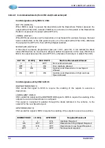
13. The programming parameters allow selecting which safety outputs use and the state
they must assume in the different machine states (Upstroke, Stop, Slow Downstroke,
Fast Downstroke). The programming parameter C15 allows selecting which outputs,
among OUTS1, OUTS2, OUTS3 and OUTS4, you wish to use as safety output
controlled by MCS and which not. The selected outputs will be controlled by MCS and
will assume, in the different machine states, the state assigned by parameters C1, C4,
C7 and C10. Those not selected, downgraded to generic power outputs, can be
controlled by CNC through RS232.
Example:
Values and corresponding meaning:
SETTING
MEANING
C15 : 1101
OUTS1, OUTS2 and OUTS4 used as safety
outputs by MCS
OUTS3 used as generic output driven by
CNC via RS232
C1 : 1100
Values assumed in High Speed
OUTS1=24V, OUTS2=24V, OUTS4=0V
C4 : 0001
Values assumed in Low Speed
OUTS1=0V, OUTS2=0V, OUTS4=24V
C7 : 0000
Values assumed in Stop
OUTS1=0V, OUTS2=0V, OUTS4=0V
C10 : 1101
Values assumed in upstroke
OUTS1=24V, OUTS2=24V, OUTS4=24V
Similarly, the programming parameter C16 allows selecting which output, among
OUTS5, OUTS6, OUTS7 and OUTS8, you wish to use as safety output controlled by
MCS and which not. The selected one will be controlled by MCS and will assume, in the
different machine states, the state assigned by the parameters C2, C5, C8 and C11.
Those not selected, downgraded to generic power outputs, can be controlled by CNC
via RS232.
38
DLAM01EN
Summary of Contents for DSP LASER AP
Page 2: ......
Page 4: ......
Page 50: ...DSP LASER AP with MCS Figure 34 44 DLAM01EN...


