


DSP LASER AP with MCS
9.
Signals and plate data
9.1.
Leds and references: scheme and functions
9.1.1. MCS module
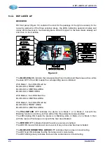
FRONT PANEL
MCS front panel (Figure 9) contains the LEDs indicating the state 1 (led on) or 0 (led off) of
the safety inputs, the LEDs indicating the state ON (led on) or OFF (led off) of the safety
outputs, the display and the keys, the digit numbering, the type and the numbering of the
inputs and the outputs connected to the corresponding connectors, the type and the value
of the power supply for the module, the numbering of some connectors.
GREEN NUMBERS 1, 2, 3, 7, 8, 9
They indicate the number of the male connector, present on the module, which the female
connector with the same number must be connected to.
Figure 9
CONNECTORS 7 and 8
INS1÷INS24 with relevant YELLOW LED:
Safety inputs with input logic level 0-1. The relevant YELLOW LED indicates if a logic level
1 (24 Vcc)=LED ON or a logic level 0 (0Vcc)=LED OFF is present in input.
DLAM01EN
17
Summary of Contents for DSP LASER AP
Page 2: ......
Page 4: ......
Page 50: ...DSP LASER AP with MCS Figure 34 44 DLAM01EN...


