


DSP LASER AP with MCS
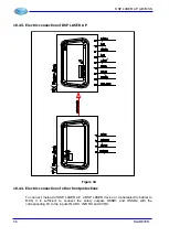
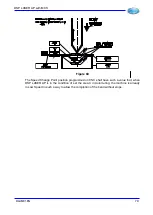
The status of all the inputs and outputs on MCS is indicated by a led or a message on the
Display. For this reason, once the system is wired, the correctness of the wiring can be
verified reading the state of the leds or the information on display.
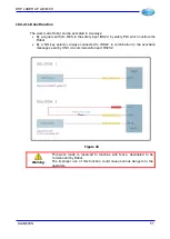
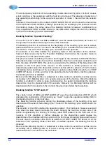
Pulsed Inputs and Outputs
The pulsed inputs must be connected to the relevant pulsed output by means of a normally
closed (NC) contact (or by means of a normally open NO contact, if you are using
photoelectric barrier) to the relevant pulsed output.
INP1
OUTP1
Caution:
If you connect a pulsed output to a pulsed input different from the
corresponding one, the system will enter in Lock state.
Caution:
The unused pulsed inputs must be connected to the relevant pulsed
outputs.
To test the correct wiring of pulsed inputs and outputs:
•
Close all the NC contacts relevant to the 8 outputs. On MCS front panel, verify that
the 8 orange leds, corresponding to the 8 pulsed inputs, are ON.
•
Open the contact relevant to OUTP1 output.
•
Verify that the orange Led relevant to the input INP1 is OFF.
•
Repeat this operation for all the 8 pulsed inputs - outputs.
Safety Inputs
There is one yellow Led located on the MCS front side per every safety input.
Mode Inputs
To verify the correct wiring of the mode selector
•
Bring the selector to position 1.
•
Verify that the Leds relevant to INS1 and INS2 are OFF.
•
Bring the selector in position 2.
•
Verify that the Led of INS1 is ON and the Led of INS2 is OFF.
•
Bring the selector in position 3.
•
Verify that the Led of INS1 is OFF and the Led of INS2 is ON.
•
Bring the selector back in position 1.
Foot Pedal Control Selector Inputs
To verify the correct wiring of the foot pedal control selectors (if present):
•
Bring the selector to position 1.
•
Verify that the Led of INS3 is ON and the Leds of INS4 and INS21 are OFF.
•
Bring the selector to position 2.
•
Verify that the Led of INS4 is ON and the Leds of INS3 and INS21 are OFF.
•
Bring the selector to position 3.
•
Verify that the Led di INS21 is ON and the Leds of INS3 and INS4 are OFF.
•
Bring the selector back in position 1.
68
DLAM01EN
Summary of Contents for DSP LASER AP
Page 2: ......
Page 4: ......
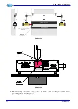
Page 50: ...DSP LASER AP with MCS Figure 34 44 DLAM01EN...


