


DSP LASER AP with MCS
Error
Code
Description of Alarm or Error
0
No alarm and error.
1
Synchronization of Ch.A and Ch.B MCS: release Foot Pedal.
2
System Error: contact the service.
3
System Error: contact the service.
4
System Error: contact the service.
5
System Error: contact the service.
6
System Error: contact the service.
7
Error in RX connection: verify that DSP AP - RX is ON and the connection of DSP AP
– RX to MCS.
8
Alarm Axes Misalignment: position of axis Y1 differs from position of axis Y2 for a
value greater than the one assigned to parameter A7 of the programming
parameters. Verify the positioning of the press and the operation and connection of
the two encoders.
9
Error Downstroke Pedal1: verify the connection of the NO (INS5) and NC (INS6)
signals of Downstroke Pedal1 and the operation of the two contacts.
A
Alarm Antipanic: release the antipanic pedal or verify the connection of the NC
signals INP1 and INP2 and the operation of the two contacts.
Note. If programmed, press the upstroke pedal to clear this error.
B
Alarm Emergency: unlock the emergency switch or verify the connection of the NC
signals INP3 and INP4 and the operation of the two contacts.
Note. Press the emergency reset button to clear this alarm.
C
Alarm High Speed: the press has exceeded the allowed high speed. Verify that the
test of the stop distance has been correctly executed and that CNC drives correctly
the proportional valves.
Note. Press the emergency reset button to clear this alarm.
D
Alarm Low Speed: the press has exceeded the allowed low speed. Verify that the
sheet edge acquisition has been correctly executed and that the speed change point
has been correctly set.
Note. Press the emergency reset button to clear this alarm.
E
Alarm Side Protections: both the side protections are open. Verify that they are
closed and that the NC signals INP5 and INP6 are correctly received. Moreover verify
the operation of the two contacts.
F
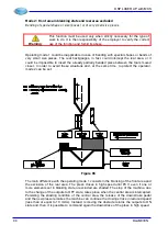
Alarm Laser Beam Obstruction: an obstacle has been detected in the protercted area
of the laser beam during the fast downstroke. Remove the obstacle or continue the
bend in low speed.
G
Problem on the system status. Verify the RS232 connection, if used, and restart the
device. If the problem persists, contact the service.
H
Error Foot Pedal Control Selector: the signals relevant to the selection of the foot
pedal controls are not correct. Verify the status of the signals INS3, INS4 and INS21.
Moreover, verify the operation of the selector contacts.
I
Error Direction: The press is moving in the wrong direction. Verify the connection of
the encoders or the hydraulic circuit.
Note. Press the emergency reset button to clear this alarm.
J
Error Emergency Relay: the signals of the monitors of emergency relays (INS15 and
INS16) do not match with the state of relays. Verify the connections of emergency
relays (OUTRL1 and OUTRL2) and of the relevant monitors (INS15 and INS16).
K
Alarm Automuting: the Automuting of DSP Laser AP device has not taken place in
the correct way. Verify the positioning of DSP Laser AP device or modify the speed
change point from CNC to allow the press going down in correct way. See chap 11.7.
96
DLAM01EN
Summary of Contents for DSP LASER AP
Page 2: ......
Page 4: ......
Page 50: ...DSP LASER AP with MCS Figure 34 44 DLAM01EN...


