


10
7. Connection of Input-Output
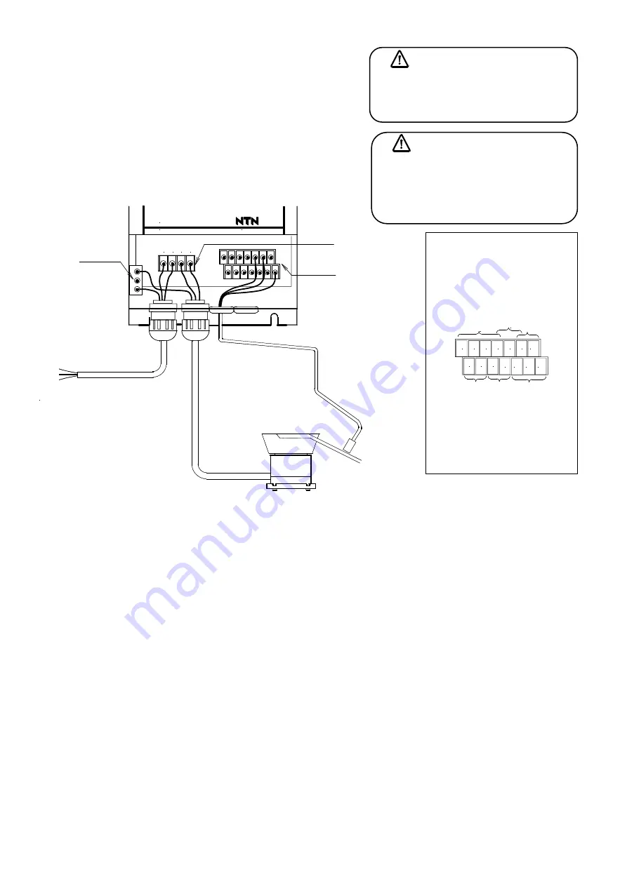
External connection diagram
(Also refer to the block
diagram in the next page)
(Details of each wiring are described in the page shown
in the notes written below, therefore please refer to them)
Caution
Please refer to the descriptions in caution for safety in P.2 to 4 and explanations for each item below for the
wiring method and cautions when wiring.
*1 Wiring of power supply
P.12
Refer to paragraph “Connection to power supply”
*2 Wiring of load
P.13 Refer to paragraph “Connection to load line”
*3 Wiring of external control input P.16 to 17 Refer to paragraph “Wiring of external control input”
*4 Wiring of overflow sensor
P.18 to 19 Refer to paragraph “Connection of sensor”
*5 Receiving of drive signal
P.21
Refer to paragraph “Wiring of drive instruction output”
*6 Others Multi-speed control P.20
Refer to paragraph “Multi-speed function”
Valve wiring
P.19
Refer to paragraph “Air blow control during driving”
Emergency signal
P.21
Refer to paragraph “Wiring of emergency signal”
*7 There is a possibility that the noise is added in the power supply line. Please take measures such as
separation of the power supply from equipments which dislike noise or insertion of noise filter.
*8
Cable length
Main circuit (L,N,1,2)
・・・
For extension, the size must be 2.5
㎟
or more and the length must be 10m or
less. Signal line
・・・
The length must be within 10m and the line must be separated from the power cable.
*9 After wiring work is completed, check the safety by protective continuity test.
Caution
Please select an appropriate type to the
kind and the size of the cable used and
responding to use conditions and the
environment.
Danger
Do the wiring work after cutting off the
main breaker without fail. It is likely to
get an electric shock.
JAPAN
V. F. CONTROLLER
アースバー
端子台
AC200-230V 50/60 12A
L N 1 2
パーツ
フィーダ
単相交流電源に接続する
(AC200~230V 50/60Hz)
緑または緑/黄はアースに
接続する
黒
黒
緑/黄
電源ケーブル
ワーク確認
センサ
負荷
リー
ド線
*1
*2
(M4ビス)
端子台
(M3ビス)
*4
Parts
feeder
*
2
Load
c
abl
e
Earth bar
*
1 Power supply cable
Red
Green/Yellow
White
It is connected to the single phase AC
power. (AC200V –230V 50/60Hz)
Connect green or green/yellow to the
earth.
*4
Work confirming
sensor
(M4 terminal screw)
Terminal block
(M3 terminal screw)
Terminal block
【
Layout of terminal board for control
】
B1
0V
IN1
C2 EM
Y1C Y1A
0V
X1
+V
24V
24V
異常信号
(マルチ出
力
)
B2
P0
運転
中信
号
速度
切替
え
信
号
外部制
御
入
力
オー
バフロ
ー
センサ
入
力
バルブ制御
出
力
*5 Pilo
t s
ig
nal
*6 Emerg
enc
y s
igna
l
(Mult
i out
put
)
*3
Ext
ernal cont
rol
in
put
*6
V
alve cont
rol out
pu
t
*4 Overflow senso
r
in
put
*6 Spe
ed s
w
itc
h
in
pu
t