- 20 -
INSTALLATION INSTRUCTIONS
G015
For NPK 500 to 1300 ft. lb. class hammers (
with fixed hammer port connections
).
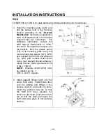
6. Install the straight adapter fitting (f1)
into the hammer grease port (
26
).
NOTE:
The grease fitting (30) is for
manual greasing.
DO NOT
install the above fitting into the
hammer’s air connection port (
17
). It is
used in underwater applications.
Pumping grease into this port will cause
damage to the hammer.
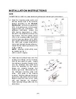
7. Route the pressure hose (a63) from
port “P
OIL
” on the grease pump (FZ)
through the hole in the hammer
bracket side plate to the hammer
pressure inlet port. Route return hose
(a64) from port “R
OIL
” on the grease
pump through the side plate hole to
the hammer return port.
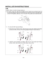
8. Fill grease line before installation (See
AUTO LUBE GREASE LINE PRE-FILLING
section of this manual.) Route the grease line (
29
) from “P
GREASE
” port on the auto
lube pump through the hole in the hammer bracket side plate to the hammer grease
port. Secure the grease hose to the support block (FV) using the supplied hose
clamp (NPK part number B600-2090), hex head cap screw (NPK part number
K007-4500) and washer (NPK part number K005-4540).
9. Using the protective hose covering (supplied by NPK), wrap the hydraulic hose
lines between the auto lube pump and the hammer.
NOTE:
Cut length to fit.


