- 11 -
GENERAL DESCRIPTION
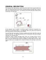
The hydraulic motor (a58) drives a worm shaft (a55), which turns a gear/eccentric unit
(a26). As the gear/eccentric unit revolves, it strokes the delivery plunger (a27), which is
part of the pumping element (a11). The stroking of the delivery plunger creates suction
and delivery of the lubricant.
As the hydraulic motor is rotated, a continuous supply of lubricant is delivered to the
hammer via the pressure channel. An integrated check valve prevents the lubricant
from being fed back into the grease pump cartridge.
To protect the Auto Lube system, the pump includes a relief valve (a3) which opens at
4060 psi (
280 bars
). The discharge opening (
157
) of the pressure relief valve is placed
opposite of the cartridge holder.
Transparent plastic reusable cartridges (a54) serve as a storage reservoir for the
lubricant. The lubricant level is checked visually by the follower piston (a66). To be
able to check the lubricant level when the cartridge is almost empty, the pump main
housing
(G025 only)
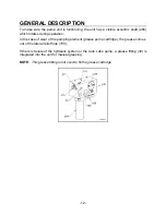
is equipped with an inspection window (
155
) as shown on the next
page.

