background image

3 - TRANSPORT OPERATIONS

3-11

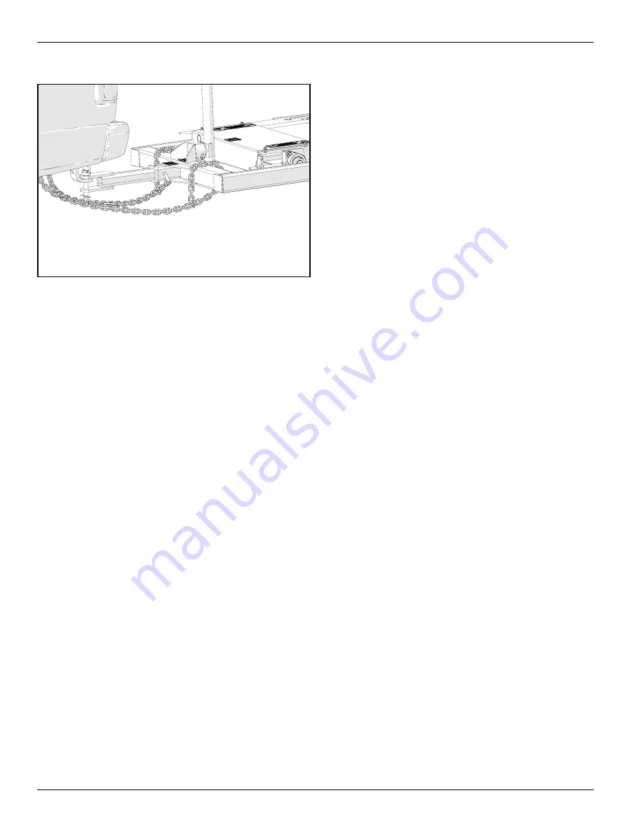
15.  Secure the safety chains around the Kwik-Pit drawbar 

cage to prevent unexpected separation. 

(See Fig. # 3-24)

Fig. # 3-24 Secure the Safety Chains Around the Kwik-Pit 

Drawbar Cage

14.  Attach other end(s) of safety chain(s) to towing vehicle. 

(See"Use a Safety Chain" on page 2-12)


15.  Tow the unit to the next location.

Detaching Kwik-Pit From The Towing Vehicle

1.   Follow the steps in reverse order defined in 

(See "Attach-

ing Kwik-Pit To Towing Vehicle" On Page 3-9)

Summary of Contents for Kwik-Pit 26 Series

Page 1: ...del 26 Series Kwik Pit Drive Over Conveyor Kwik Pit Drive Over Conveyor Model 26 Series Shown With Hydraulic Drive Kit in Lowered Position With Flaps Down Kwik Pit Drive Over Conveyor Model 26 Series...

Page 2: ......

Page 3: ...cautions in this manual and all other manuals for products associated with this planter as well as in all on product warning decals Failure to do so could result in death or serious injury or property...

Page 4: ...heel and Tire Safety 2 7 Remove Paint Before Welding or Heating 2 7 Avoid Heating Near Pressurized Fluid Lines 2 7 Avoid Overhead Power Lines 2 8 Electrical Storm Safety 2 8 Working at Heights If Appl...

Page 5: ...of 2 4 2 Machine Components Page 2 of 2 4 3 Machine Components 4 3 MACHINE BREAK IN 4 4 PRE OPERATION CHECKLIST 4 4 Jack 4 5 Connecting Hydraulic Hoses To Tractor 4 6 Lift Axle Raise Lower Control Lev...

Page 6: ...heck Tire Pressure 5 21 Check The Hydraulic Oil Level 5 22 Oil The Chain Coupler 5 23 Inspect Drive Over Hopper Cable 5 24 Change Hydraulic System Oil 5 25 Inspect The Inlet Flashing 5 27 Clean and Wa...

Page 7: ...is imperative that this machine is operated in accordance with the procedures outlined in this manual 1 0 GENERAL INFORMATION Note to the Owner This manual contains important information about the saf...

Page 8: ...lways give your authorized Kwik Pit dealer the Model Number and Serial Number of your Kwik Pit product when ordering parts requesting service or any other information to provide the most efficient ser...

Page 9: ...4 as mentioned throughout the manual are determined when standing at the rear of the tractor and looking toward the forward direction of travel Fig 1 5 4 3 2 1 Determining Orientation Using Direction...

Page 10: ...1 4 1 GENERAL INFORMATION This Page Is Intentionally Left Blank...

Page 11: ...dous situation which if not avoided could result in minor or moderate injury CAUTION may also be used to alert against unsafe practices associated with events which could lead to personal injury The c...

Page 12: ...erating the machine on slopes Raised equipment partially full or full conveyor belt and other loads will change the center of gravity of the machine The machine can tip or roll over when near ditches...

Page 13: ...chine Transport Service locks can be used for this purpose Shut off tractor engine and remove key when working on machine If air has been allowed to enter hydraulic hoses or cylinders bleed hydraulic...

Page 14: ...hoses If hydraulic fluid penetrates the skin seek medical attention immediately Any fluid injected into the skin must be surgically removed within a few hours or gangrene may result Doctors unfamilia...

Page 15: ...ransporting Electrocution can occur without direct contact 11 Be sure that area around machine is clear before raising or lowering the machine 12 Empty Kwik Pit from all material before moving 13 Avoi...

Page 16: ...on a level surface engage park brake place transmission in PARK shut off engine remove key and wait for all moving parts to stop before leaving vehicle cab If machine is detached from a towing vehicle...

Page 17: ...d to manufac turer s recommendations Never reinflate a tire that has been run flat or seriously un der inflated without removing the tire from the wheel Have the tire and wheel closely inspected for d...

Page 18: ...y under overhead power lines and around utility poles Know the transport height of all your equipment Electrocution can occur without direct contact with overhead electrical lines Electrical Storm Saf...

Page 19: ...nts Avoid filling tanks using cans which may cause considerable spillage In general avoid skin contact with all fuels oils acids sol vents etc Most of them contain substances which may be harmful to y...

Page 20: ...ling or disposal of waste fluids example oil fuel coolant brake fluid filters batteries and other substances or parts Burning of flammable fluids or components in other than specially designed inciner...

Page 21: ...duce speed when towing un der adverse surface conditions when turning and when on inclines Do Not attempt transport if the fully loaded implement weighs more than 1 5 t 3 300 lb and more than 1 5 time...

Page 22: ...hem to an interchangeable part of the hitch assembly Attach hooks up from underneath the S Hook holes or slots Do not just drop into hole or slot 4 Provide enough slack in chains to permit tight turns...

Page 23: ...than 1 5 times the tractor weight If towed equipment has brakes do not travel more than 25 mph 40 km h and do not tow loads more than 4 5 times the tractor weight Ensure the load does not exceed the...

Page 24: ...ace Hazard Area WORK AREA AUTHORIZED PERSONNEL ONLY OVERHEAD WIRES KEEP AWAY KEEP OUT OF SHADED HAZARD AREA CRUSH HAZARD BETWEEN TRACTOR IMPLEMENT KEEP OUT PTO HAZARD KEEP OUT EXPOSED CONVEYOR BELT HA...

Page 25: ...kup Fully raise the machine by fully extending the lift wheel axle cylinders See Lift Axle Raise Lower Control Le ver On Page 4 7 and install the transport locks before transporting See Transport Lock...

Page 26: ...ort speed for this implement of 20 mph 32 km h Reduce speed on rough roads and surfaces 9 Stay away from overhead obstructions and power lines when staging equipment Electrocution can occur with out d...

Page 27: ...e Option 10 11 13 12 14 2 5 1 3 4 5 6 10 6 5 9 5 8 7 Item Part Number Description Qty Item Part Number Description Qty 1 90 44 0262 Decal Safety Information 1 8 90 44 0269 Decal Notice Wheel Movement...

Page 28: ...Service Pin 2 6 90 44 0566 Decal Warning Slip Hazard Kwik Pit 2 15 90 44 0350 Decal Electrocution Hazard 1 7 90 44 0257 Decal Warning Transport Hazard 1 16 90 44 0268 Decal Hydraulic Oil Only AW32 1 8...

Page 29: ...quipment Only trained personnel may assemble operate or maintain the equipment Children and untrained personnel must be kept outside of the work area If the manual guards or decals are missing or dama...

Page 30: ...ig 2 9 WARNING HIGH PRESSURE FLUID HAZARD TO PREVENT SERIOUS INJURY OR DEATH 1 Relieve pressure on system before repairing adjusting or disconnecting 2 Wear proper hand and eye protection when searchi...

Page 31: ...FORMATION 2 21 Fig 2 11 Danger Decal P N 90 44 0396 Fig 2 12 Safety Decal Location CRUSH HAZARD TO PREVENT SERIOUS INJURY OR DEATH Stand clear when raising or lowering the swing conveyor 90 44 0369 Se...

Page 32: ...3 WARNING Improper operation or maintenance can result in serious injury or death Read and understand the Operator s Manual and all safety signs before using or maintaining the machine If you do not u...

Page 33: ...injury or death DO NOT step on or touch moving conveyor belt Turn machine OFF shut down and lock out power source unplug power cord and wait for all moving parts to stop before inspecting servicing o...

Page 34: ...NSPORT LOCK STOW POSITI ON TRANS PORT LOCK LOCK POSITI ON TRANS PORT LOCK STOW PO SIT ION TR AN SP OR T LO CK LO CK PO SIT ION TR AN SP OR T LO CK Fig 2 20 Safety Decal Location See Fig 2 18 STOW POSI...

Page 35: ...2 SAFETY INFORMATION 2 25 Fig 2 21 Warning Decal P N 90 44 0566 Fig 2 22 Safety Decal Location See Fig 2 21 See Fig 2 21...

Page 36: ...2 SAFETY INFORMATION 2 26 Fig 2 23 Warning Decal P N 90 44 0167 Fig 2 24 Safety Decal Location See Fig 2 23 See Fig 2 23...

Page 37: ...chine OFF shut down and lock out power source unplug power cord and wait for all moving parts to stop before inspecting servicing or repairing machine Keep body hair and clothing away from moving conv...

Page 38: ...2 SAFETY INFORMATION 2 28 Fig 2 29 Warning Decal P N 90 44 0257 Fig 2 30 Safety Decal Location See Fig 2 29...

Page 39: ...FETY INFORMATION 2 29 Fig 2 31 Warning Decal Large P N 90 44 0538 SLIP HAZARD Can cause injury or damage to equipment DO NOT use belt guard as a step 90 44 0258 See Fig 2 31 Fig 2 32 Safety Decal Loca...

Page 40: ...ION HAZARD 1 Turn machine OFF shut down and lock out power source unplug power cord and wait for all moving parts to stop before servicing or repairing electrical components 2 Keep electrical componen...

Page 41: ...2 SAFETY INFORMATION 2 31 Fig 2 35 Warning Decal Large P N 90 44 0538 Fig 2 36 Warning Decal Location See Fig 2 35 Important Notice Informational Decal Locations...

Page 42: ...YOR BELT SPEED CONTROL VALVE CONVEYOR BELT SPEED CONTROL LEVER HO PP ER FLA PS RA ISE LO WE R LE VE R LIF T AX LE RA ISE LO WE R LE VE R 90 4 4 05 65 Fig 2 37 Informational Decal P N 90 44 0564 Fig 2...

Page 43: ...PS RAIS E LOW ER LEVER LIF T AXLE RAIS E LOW ER LEVER 90 4 4 05 65 HO PP ER FLA PS RA ISE LO WE R LE VE R LIF T AX LE RA ISE LO WE R LE VE R 90 4 4 05 65 Fig 2 39 Informational Decal P N 90 44 0565 Fi...

Page 44: ...2 SAFETY INFORMATION 2 34 Fig 2 41 Informational Decal P N 90 44 0568 Fig 2 42 Informational Decal Location See Fig 2 41...

Page 45: ...quire ments for roadway transport it may be impossible for this implement to be approved for such roadway transport The customer is responsible for understanding and complying with all local regional...

Page 46: ...2 SAFETY INFORMATION 2 36 This Page Is Intentionally Left Blank...

Page 47: ...transport speed for this implement of 20 mph 32 km h Reduce speed on rough roads and surfaces 9 Stay away from overhead obstructions and power lines when staging equipment Electrocution can occur wit...

Page 48: ...detailed information as procedures vary by equipment Determine Tractor Requirements Fig 3 3 Determine Tractor Requirements For optimum performance see Tractor Engine Power Requirements in the Specifi...

Page 49: ...ree Point Hitch Position Drawbar Fig 3 5 Standard Drawbar in Transport Position CAUTION Avoid personal injury or death to you or others due to lost machine steering control Always pin the drawbar in t...

Page 50: ...nts IMPORTANT Towing vehicle drawbars hitch receivers must be com patible with the Kwik Pit hitch Refer to the Tractor Pickup Truck Operator s Manual for specific drawbar hitch receiver requirements D...

Page 51: ...iver with S Hook holes or slots of sufficient rating B Hitch Ball Mount of sufficient rating and correct rise or drop C 1 0 Pin with retainer D Safety Chains A D B C Fig 3 10 Pickup Truck Requirements...

Page 52: ...3 If you would like to purchase the components to assemble your Supply and Return hoses yourself use the following tables below 90 37 1576 Hose 08 x XX X OAL 08 FJX x 08 MO Return Kwik Pit ITEM PART...

Page 53: ...erence only Ensure machine performance by using only tires specified for your ma chine and inflating them to correct pressures Tire Size Load Speed Index Pressure psi kPa bar 235 80R16 126L 80 551 5 5...

Page 54: ...from the clutch can lead to injury or death to the person standing nearby DANGER CRUSH HAZARD Stand clear when raising or lowering the Kwik Pit Keep feet legs and body clear when raising and lowering...

Page 55: ...damage kinks age and exposure Check hoses regularly Replace damaged hoses IMPORTANT All hydraulic couplers must be clear of debris dust and sand Foreign material can damage hydraulic system 4 Hydrauli...

Page 56: ...lectrical box Unplug the pow er cord wrap it around frame and secure it to prevent dragging 12 If the Standard Hitch A was removed during operation then re install the Standard Hitch A Bent Pull Clevi...

Page 57: ...3 24 Secure the Safety Chains Around the Kwik Pit Drawbar Cage 14 Attach other end s of safety chain s to towing vehicle See Use a Safety Chain on page 2 12 15 Tow the unit to the next location Detac...

Page 58: ...3 TRANSPORT OPERATIONS 3 12 This Page Is Intentionally Left Blank...

Page 59: ...nplugging any area of the machine 4 Clear the area of bystanders especially children before starting 5 Be familiar with the machine hazard area If anyone enters hazard area shut down machine immediate...

Page 60: ...harge Hood 8 Kwik Pit Hitch Receiver 24 Wheel Assembly 9 Lift Axle Assembly 25 Drive Over Hopper Hydraulic Cylinder 10 Drive Over Ramp 26 Hydraulic Motor 11 Inlet Cover 27 Discharge Section 12 Jack 28...

Page 61: ...Drawbar Cage 17 Transition Rollers 29 Hopper Flaps Raise Lower Lever 6 Hopper Pulley 18 Drive Over Hopper Cable 30 Conveyor Belt Speed Lever 7 Kwik Pit Hitch 19 Operator s Manual Canister 31 Return R...

Page 62: ...eck the drive belt tension and tension as required See Tension And Alignment of the Drive Belts on page 5 35 6 Check the conveying belt tension and alignment Tension or align as required See Conveyor...

Page 63: ...Jack A is located where shown See Fig 4 3 C B Turn CCW To Lower Hitch End Turn CW To Raise Hitch End D A E F Fig 4 3 Jack Fig 4 4 Lift Axle Raise Lower Control Lever Location Lower Raise Lift Axle Rai...

Page 64: ...ne Hydraulic Hose Polarity Pressure Or Return Hose Grip Hose Grip 2 Use the hydraulic hoses identified here to connect to the tractor RETURN HOSE SUPPLY HOSE Fig 4 6 Identifying Hydraulic Hoses To Con...

Page 65: ...he Lift Axle Wheel Assemblies B to lower about the Rotation Point C thereby raising the machine See Fig 4 9 A C B Fig 4 9 Raising The Machine IMPORTANT When raising the Kwik Pit it will be necessary t...

Page 66: ...aise position See Fig 4 12 the Drive Over Hopper Cable Hydraulic Cylinder A will retract pulling the Drive Over Hopper Cable B and cause the LH Flopper Flap C RH Hopper Flap D to raise forming a 3 sid...

Page 67: ...he conveyor belt can travel 1 One is the Minimum and 0 Zero is OFF Fig 4 18 Conveyor Belt Speed Settings 0 ZERO OFF SPEED 1 10 Max Speed Conveyor Belt Speed The best results are obtained when the driv...

Page 68: ...cedures and equipment vary The end user will need to have a licensed electrician to provide power to the machine per the National Electrical Code ANSI NFPA 70 and local codes Install an ON OFF switch...

Page 69: ...es the Lift Axle Raise Lower Control C and the Hopper Flaps Raise Lower Control D See Fig 4 23 The Hydraulic System Power Lever A is located where shown See Fig 4 21 D C B DISENGAGE ENGAGE A Fig 4 21...

Page 70: ...OW PO SIT ION TRAN SPOR T LO CK LO CK PO SIT ION TRAN SPOR T LO CK Install transport locks on left and right side of the lift axles to avoid cylinders settling during transport or servicing FAILURE TO...

Page 71: ...3 Review the Workplace Hazards schematics and use extra care when inside the hazard area Keep all spectators and bystanders out of this area Should anyone enter this area stop the machine immediately...

Page 72: ...the Discharge Spout A is over the Intake of the Secondary Conveyor B or conveying system See Fig 4 27 A B Fig 4 27 Working Position Position Discharge Spout Over Intake Of Secondary Conveyor 7 Unhook...

Page 73: ...Page 4 9 which will stop the conveyor belt from traveling Electric Drive Wet Kit Option Turn the electric motor switch OFF to interrupt power to the Kwik Pit conveyor belt Wet Kit See Master Disconnec...

Page 74: ...Fig 4 32 Rear Dumping Grain Truck In Position 7 Center the Grain Truck Discharge Gate over the Kwik Pit Conveyor Belt See Fig 4 33 See Fig 4 34 Fig 4 33 Center the Grain Truck Discharge Gate Over the...

Page 75: ...into the Intake Hopper 10 Ensure that LH RH Hopper Flaps are in the fully lowered position before moving the grain truck to the next bin gate if obstructed and driving truck off of the Drive Over Ram...

Page 76: ...t hopper Material Loading Area To achieve maximum capacity 1 Direct the flow of Material A into the Intake Hopper B between the 2 Arrows C for the best capacity See Fig 4 37 C B A Fig 4 37 Bottom Dump...

Page 77: ...ds 4 Hydraulic Drive Models Since the start up torque loads are so much higher than normal when the conveyor belt ing is full restart at low speed Do not let the conveyor belt drive roller spin on the...

Page 78: ...that can be caused by conveying fer tilizer 1 Do not allow fertilizer to fill over the edge of the belt This will allow fertilizer to get under the belt and start building up 2 Reduce the flow of mate...

Page 79: ...are properly grounded Use adequate light for the job at hand 5 Before applying pressure to a hydraulic system make sure all components are tight and that hoses and couplings are in good condition 6 R...

Page 80: ...any worn cut abraded flattened or crimped hoses If hydraulic fluid penetrates the skin seek medical attention immediately Any fluid injected into the skin must be surgically removed within a few hour...

Page 81: ...g Keep hands feet and clothing away from power driven parts Disengage all power and operate controls to relieve pressure Lower equipment to the ground Stop the engine Remove the key Allow machine to c...

Page 82: ...operly Always lower the attachment or implement to the ground before you work on the machine If the work requires that the machine or attachment be lifted provide secure support for them If left in a...

Page 83: ...e only the wheel hubs are greasable They require minimal lubri cant Recommended greasing is 1 small stroke every 2 weeks Be careful not to over grease as this may push the seal out 4 Replace and repai...

Page 84: ...Alignment X X 50 Hours Or Weekly 5 7 Check Wheel Flange Bolt Torque 12 X X 5 15 Check Tightness Of All Bolts Cap Screws X X 100 Hours Or Monthly 5 17 Check Roller Lagging X X 5 18 Inspect Hopper Flaps...

Page 85: ...n PARK shut off engine remove key and wait for all moving parts to stop before leaving the tractor cab Electric Drive Option Turn machine OFF shut down and lock out power source unplug power cord and...

Page 86: ...for all moving parts to stop before leaving the tractor cab Electric Drive Option Turn machine OFF shut down and lock out power source unplug power cord and wait for all moving parts to stop before in...

Page 87: ...uts 7 Check belt tension by running conveyor belt slowly for one 1 minute If belt is not slipping then proceed to next step otherwise repeat previous steps 8 If belt tracks to either side abruptly the...

Page 88: ...e Keep body hair and clothing away from moving con veyor belt and rollers Do not operate with any guards removed or modified Keep guards in good working order Failure to comply could result in death o...

Page 89: ...sen Bearing Nuts A and Jam Nuts B at the hopper pulley See Fig 5 5 A A B Fig 5 10 Adjusting Conveyor Belt Tension At Hopper Pulley 2 Adjust the conveyor belt alignment by tightening or loos ening the...

Page 90: ...oller 2 3 See Fig 5 13 A 2 A A 1 A A 3 A Fig 5 13 Adjusting Conveyor Belt At Transition Rollers 2 Adjust the conveyor belt alignment by tightening or loos ening the Adjustment Bolt C Adjust one side o...

Page 91: ...e Option 2 Adjust the conveyor belt alignment by tightening or loos ening the Adjustment Bolt C Adjust one side of pulley at a time See Fig 5 18 See Fig 5 19 IMPORTANT If a conveyor belt is out of ali...

Page 92: ...A Fig 5 21 Tighten Bearing Nuts Electric Drive Option A A 4 Start the conveyor and run the conveyor belt slowly for one 1 minute 5 If belt is centered continue to the next step if not repeat the alig...

Page 93: ...e torque charts at the back of this manual for proper torque unless otherwise specified in this manual See Torque Fasteners On Page 7 3 Every 10 Hours Or Each Day Visually Inspect The Equipment 1 If t...

Page 94: ...essure can penetrate the skin causing death or serious injury or infection DO NOT use your hand to check for leaks Use a piece of cardboard or plywood WARNING Hydraulic Drive Option Engage park brake...

Page 95: ...tor cab Electric Drive Option Turn machine OFF shut down and lock out power source unplug power cord and wait for all moving parts to stop before inspecting servicing or repairing machine Keep body ha...

Page 96: ...aving the tractor cab Electric Drive Option Turn machine OFF shut down and lock out power source unplug power cord and wait for all moving parts to stop before inspecting servicing or repairing machin...

Page 97: ...ause leaks Make sure to use steel fittings approved for use with the hose manufacturer When replacing hoses use fittings of the correct size and thread to prevent leaks 1 If the machine is in the rais...

Page 98: ...cab Electric Drive Option Turn machine OFF shut down and lock out power source unplug power cord and wait for all moving parts to stop before inspecting servicing or repairing machine Keep body hair...

Page 99: ...machine and inflating them to correct pressures Tire Size Load Speed Index Pressure psi kPa bar 235 80R16 E 80 551 5 5 Fig 5 30 Table Tire Pressure Chart 1 If the machine is in the raised position In...

Page 100: ...the tractor cab Electric Drive Option Turn machine OFF shut down and lock out power source unplug power cord and wait for all moving parts to stop before inspecting servicing or repairing machine Kee...

Page 101: ...ing con veyor belt and rollers Do not operate with any guards removed or modified Keep guards in good working order Failure to comply could result in death or serious injury 2 Apply a light coat of SA...

Page 102: ...sion in PARK shut off engine remove key and wait for all moving parts to stop before leaving the tractor cab Electric Drive Option Turn machine OFF shut down and lock out power source unplug power cor...

Page 103: ...ing con veyor belt and rollers Do not operate with any guards removed or modified Keep guards in good working order Failure to comply could result in death or serious injury WARNING HOT LIQUID HAZARD...

Page 104: ...om the top Use an ISO grade 36 hydraulic oil for all operating conditions Hydrex MV36 or comparable See Fig 5 38 Oil Fill Level Fig 5 38 Check The Hydraulic Oil Level 10 Run the system for 1 2 minutes...

Page 105: ...ut off engine remove key and wait for all moving parts to stop before leaving the tractor cab Electric Drive Option Turn machine OFF shut down and lock out power source unplug power cord and wait for...

Page 106: ...e tractor cab Electric Drive Option Turn machine OFF shut down and lock out power source unplug power cord and wait for all moving parts to stop before inspecting servicing or repairing machine Keep b...

Page 107: ...plug power cord and wait for all moving parts to stop before inspecting servicing or repairing machine Keep body hair and clothing away from moving con veyor belt and rollers Do not operate with any g...

Page 108: ...ransmission in PARK shut off engine remove key and wait for all moving parts to stop before leaving the tractor cab Electric Drive Option Turn machine OFF shut down and lock out power source unplug po...

Page 109: ...acement belt to the belt end being removed See Fig 5 48 Attach New Belt To This End Belt Pull Out Old Fig 5 48 Thread New Belt 9 Pull the old belt out and the new belt will be threaded into place 10 D...

Page 110: ...mission in PARK shut off engine remove key and wait for all moving parts to stop before leaving the tractor cab Electric Drive Option Turn machine OFF shut down and lock out power source unplug power...

Page 111: ...ips The cut belt MUST have a square end IMPORTANT If the belt is not cut off truly square improper belt tracking will occur and serious belt damage can result Always use a large T square or equivalent...

Page 112: ...the lacing pin and bend the ends of the lacing pin away from belt travel direction A Fig 5 57 Install The Lacing Pin 8 Crimp the Retainer clips C onto each end of the Lacing Pin L using an Adjustable...

Page 113: ...or repairing machine Keep body hair and clothing away from moving con veyor belt and rollers Do not operate with any guards removed or modified Keep guards in good working order Failure to comply cou...

Page 114: ...tion Engage park brake place transmission in PARK shut off engine remove key and wait for all moving parts to stop before leaving the tractor cab Electric Drive Option Turn machine OFF shut down and l...

Page 115: ...ailure to comply could result in death or serious injury Follow these steps to repack the wheel bearings Refer to See Fig 5 64 1 Block wheels and ensure unit is stable 2 Remove the wheel bolts 1 and t...

Page 116: ...5 MAINTENANCE 5 38...

Page 117: ...on of the components in the hydraulic system Repair replace or adjust as required Tighten any loose fittings Replace any hose that is badly cut nicked or abraded or is separating from the crimped end...

Page 118: ...5 MAINTENANCE 5 40 This Page Is Intentionally Left Blank...

Page 119: ...ty and warm belt to de ice Excessive conveyor belt edge fraying Belt not aligned Align belt See Conveyor Belt Alignment on page 5 10 Conveyor belt loose Belt stretches over time Re tension belt See Te...

Page 120: ...6 TROUBLESHOOTING 6 2 This Page Is Intentionally Left Blank...

Page 121: ...Pit Model Hydraulic Requirements 26 Series Hydraulic Drive 16 gpm 3000 psi 206 bar 20 684 kPa A tractor hydraulic system with ISO hydraulic couplers is required and 1 tractor SCV is required for opera...

Page 122: ...7 Flared Fittings O Ring Boss Plugs Adjustable Fitting Lock Nuts Swivel JIC 37 Seats Size Tubing OD Thread Size ft lbs Nm ft lbs Nm Inches mm Min Max Min Max Min Max Min Max 4 1 4 6 4 7 16 20 9 12 12...

Page 123: ...rade 2 Grade 5 Grade 8 See Note Below Bolt Head Identification See Note Below Bolt Size ft lbs ft lbs Lubricated ft lbs ft lbs Lubricated ft lbs ft lbs Lubricated 1 4 3 6 2 7 8 5 6 3 11 9 8 9 5 16 7 4...

Page 124: ...lass No 8 8 10 9 12 9 Bolt Head Identification See Note below Bolt Size ft lbs ft lbs Lubricated ft lbs ft lbs Lubricated ft lbs ft lbs Lubricated M5 4 6 3 4 6 5 4 9 7 6 5 7 M6 7 7 5 8 11 1 8 3 12 9 9...

Page 125: ...not operate or allow anyone else to operate this equipment until this document has been read Review this information annually before the season start up Make periodic reviews of SAFETY and OPERATION...

Page 126: ...8 FORMS AND DECLARATIONS 8 2 This Page Is Intentionally Left Blank...

Page 127: ..._ Tire Pressure _____ Safety Chain Installed _____ Fasteners Tight _____ Review Operating Safety Instructions _____ All Decals Installed _____ Operator Manual Supplied Warranty Registration Dealer Ins...

Page 128: ...58047 within thirty 30 days Warranty Period Private Farm Use One 1 year from date of purchase Commercial Custom or Rental Use Ninety 90 days from date of purchase Replacement Parts Ninety 90 days from...

Page 129: ...nment 2 9 CONTROLS 4 5 Customers A Message to Our 1 1 D DAILY 5 15 5 16 Date Of Purchase 1 2 DECLARATIONS FORMS AND 8 1 Decommissioning Proper Recycling and Disposal of Fluids and Components 2 10 Defi...

Page 130: ...l Safety 2 9 Non Permissible Use 2 6 Note to the owner 1 1 Note to the Owner 1 1 O Observe Maximum Transport Speed 2 11 Operator Orientation 1 3 P Personal Protective Equipment PPE 2 5 Personal safety...

Page 131: ...stener 7 3 Tow Loads Safely 2 13 Tractor Engine Power Requirements 7 1 TRANSPORT OPERATIONS 3 1 Transport Safety 2 16 3 1 TROUBLESHOOTING 6 1 Troubleshooting Field Problems 6 1 U Use a Safety Chain 2...

Page 132: ......

Page 133: ...in Office Toll Free 800 446 0316 www norwoodsales com Norwood Sales Inc Cooperstown ND 701 797 3684 701 797 3685 Norwood Sales Inc Horace ND 701 588 4000 701 588 4004 Norwood Sales Inc Union NE 402 26...

Reviews: