


Connecting power
38
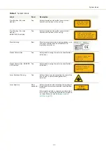
Note:
When no accessories are connected to the ACOUSTIK system as is the
typical case, place the bus defeater on the rear panel External bus connector of
the ACOUSTIK.
Figure 15
External bus defeater
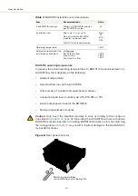
Connecting power
Power is supplied to an ACOUSTIK system through its rear AC input connector.
The connector is a standard C14 inlet designed for use with a C13 AC power cord.
Electrical and cable specifications are listed in
Table 4
Power specifications
Connecting modulation signals
Input and output wavelength modulation signals are described in the document:
Koheras BASIK Product Guide
Connect modulation signals to the D-sub 9 pin connector on the rear panel, see
“Modulation input/output” on page 85
for the pin assignments of the connector.
Connecting the trigger input or output
The laser includes a trigger logic input/output pin of the
Modulation
connector
). When uses as an input, a signal on the pin 1 of the connector can
trigger emission, and when set as an output, a signal on the pin indicates laser
emission.
Item
Description
Maximum power
consumption
300 W
AC mains Input
100-240 VAC @ 50-60 Hz
AC connector (inlet)
IEC 60320 C14 connector
Power cord
Regional AC power cord with IEC 60320 C-13 connector.
Summary of Contents for Koheras ACOUSTIK
Page 1: ...Item 800 633 01 Koheras ACOUSTIK PRODUCT GUIDE Multi Channel Modular Laser System...
Page 10: ...10...
Page 14: ...14...
Page 16: ...16...
Page 26: ...System labels 26...
Page 28: ...28...
Page 34: ...Operating and storage environment 34...
Page 42: ...42...
Page 78: ...Module overview 78...
Page 80: ...80...
Page 82: ...82 Figure 44 Mechanical dimensions 483 00 45 00 302 50 4 50 125 00 2...
Page 92: ...Installing CONTROL 92...
Page 95: ......
Page 96: ...1 Koheras ACOUSTIK Product Guide Revision 1 0 09 2021 W 10456...


