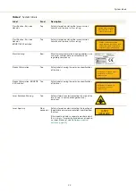


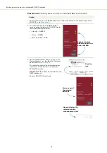

39
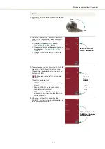
Connecting the trigger input or output
Input trigger
When the trigger pin is set as an input, a positive active high signal applied to the
trigger pin enables emission. The diagram
shows a schematic of the
trigger input.
Figure 16
Trigger input circuit
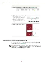
Output trigger
When the trigger feature is sets the pin as an output, the trigger pin should be
connected to an external pull-up resistor. The diagram shown in
a schematic of the trigger output circuit.
Figure 17
Trigger output circuit
Trigger signal
Based on the schematics of
and
, high and low voltage levels
can be calculated by the equations:
Vhigh = Vexternal
Vlow = Vexternal x 22k / (22k + R)
Summary of Contents for Koheras ACOUSTIK
Page 1: ...Item 800 633 01 Koheras ACOUSTIK PRODUCT GUIDE Multi Channel Modular Laser System...
Page 10: ...10...
Page 14: ...14...
Page 16: ...16...
Page 26: ...System labels 26...
Page 28: ...28...
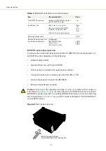
Page 34: ...Operating and storage environment 34...
Page 42: ...42...
Page 78: ...Module overview 78...
Page 80: ...80...
Page 82: ...82 Figure 44 Mechanical dimensions 483 00 45 00 302 50 4 50 125 00 2...
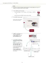
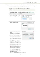
Page 92: ...Installing CONTROL 92...
Page 95: ......
Page 96: ...1 Koheras ACOUSTIK Product Guide Revision 1 0 09 2021 W 10456...


