49
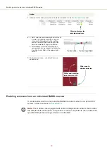
Enabling emission from all modules
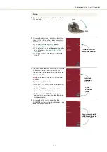
3 Ensure the front panel key switch is set to the
ON position.
4 Observe the
Interlock
indicator in the
status
panel
, if it is RED and the
Status
indicator is
AMBER, check for the following conditions:
a
The door interlock circuit is open –
Connecting the safety interlock
b
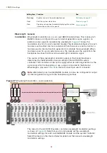
The external bus is not looped back with a
bus defeater –
c
The key switch is set to OFF – return to
step 3.
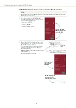
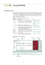
5 To enable emission for all inserted ACOUSTIK
modules, click the Emission button once.
The emission indicator (next to the Emission
button) is lit RED.
NOTE:
Emission is enabled for all inserted
modules.
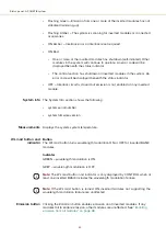
The Status indicator is lit:
•
GREEN – all laser modules are operating
normally.
•
Flashing GREEN – at least one laser
module has not stabilized.
•
RED – a system ERROR or interlock
opened with emission enabled. (Emission
will be disabled.)
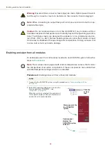
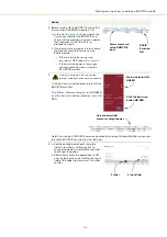
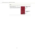
6 Observe that the status panel (for the
ACOUSTIK system) is shown with indicators in
the emission enabled state.
Action
ON
OFF
Interlock
: ON RED
Status
: ON AMBER
Interlock
Indicator
GREEN
Click
Emission
(ON)
Status
indicators lit
GREEN and
Emission
Enabled lit RED
Summary of Contents for Koheras ACOUSTIK
Page 1: ...Item 800 633 01 Koheras ACOUSTIK PRODUCT GUIDE Multi Channel Modular Laser System...
Page 10: ...10...
Page 14: ...14...
Page 16: ...16...
Page 26: ...System labels 26...
Page 28: ...28...
Page 34: ...Operating and storage environment 34...
Page 42: ...42...
Page 78: ...Module overview 78...
Page 80: ...80...
Page 82: ...82 Figure 44 Mechanical dimensions 483 00 45 00 302 50 4 50 125 00 2...
Page 92: ...Installing CONTROL 92...
Page 95: ......
Page 96: ...1 Koheras ACOUSTIK Product Guide Revision 1 0 09 2021 W 10456...


