

FORM NO. 56043055 / HR 2800, HR 2800C / BR 700, BR 700C
- 57
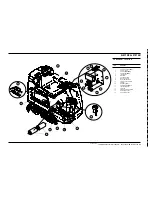
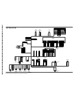
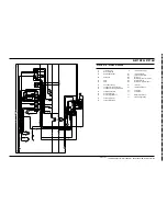
ELECTRICAL SYSTEM
Horn Switch (20):
This switch is used to momentarily activate either the pad/brush lift actuator or the squeegee lift actuator. See the descriptions below
for more details.
Scrub Off Switch (15):
This switch is used to toggle the state of the pad/brush motor. Pressing and releasing this switch will alternately turn the pad/brush motor
on and off . The indicator (9) provides the following status information:
Off
- Pad/brush output is off and there is no current flow through the contactor coil and no pad/brush motor current sensed.
Green
- Pad/brush output is on and there is normal current flow through the contactor coil and normal pad/brush motor current sensed.
Flashing red
- Either the pad/brush motor output is off and there is current flow through the coil or pad/brush motor current is sensed
(shorted output driver, control error, shorted contactor, wiring error) or the pad/brush motor output is on and there is no current flow
through the coil or no pad/brush motor current is sensed (open circuit, open relay coil, open contactor contacts, wiring error or open output
driver).
Normal Scrub Switch (16):
This switch is used to control the output to the pad/brush lift actuator. Pressing and releasing this switch will cycle the actuator output
through 4 states. These are:
1 - output off, direction = up
2 - output on, direction = down
3 - output off, direction = down
4 - output on, direction = up
When the output is in state 1, the actuator output is turned off. The pad actuator up indicator (5) will be lit and the normal scrub indicator
(10) should be off. If the indicator (10) is flashing yellow, this indicates that the control is sensing current flow through the actuator (shorted
output driver, control error). If the up indicator (5) is flashing, this indicates that the pad/brush lift system is currently selected. This means
that it is possible to momentarily activate the actuator output using the horn switch (20) This can be used to jog the actuator to allow precise
positioning of the actuator. NOTE: the actuator can only move in this situation if it is not at its up limit.
When the output is in state 2, the actuator output is turned on.The pad actuator down indicator (6) will be lit and the normal scrub indicator
(10) should be green or flashing green. The indicator will be a steady green if the control senses current flow through the actuator. It
will flash green if no actuator current flow is sensed (actuator at limit, open circuit, open output driver). The horn switch has no effect
in this state.
When the output is in state 3, the actuator output is turned off. The pad actuator down indicator (6) will be lit and the normal scrub indicator
(10) should be off. If the indicator (10) is flashing yellow, this indicates that the control is sensing current flow through the actuator (shorted
output driver, control error). If the down indicator (6) is flashing, this indicates that the pad/brush lift system is currently selected. This
means that it is possible to momentarily activate the actuator output using the horn switch (20) This can be used to jog the actuator to
allow precise positioning of the actuator. NOTE: the actuator can only move in this situation if it is not at its down limit.
When the output is in state 4, the actuator output is turned on.The pad actuator up indicator (5) will be lit and the normal scrub indicator
(10) should be green or flashing green. The indicator will be a steady green if the control senses current flow through the actuator. It
will flash green if no actuator current flow is sensed (actuator at limit, open circuit, open output driver). The horn switch has no effect
in this state.
SERVICE TEST MODE FOR MACHINES AFTER SERIAL NUMBER 1362501
(CONTINUED)
revised 2/05
Summary of Contents for Hydro-Retriever 2800 BR700
Page 2: ......


