24
-
FORM NO. 56043055 / HR 2800, HR 2800C / BR 700, BR 700C
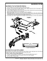
SCRUB BRUSH SYSTEM
FRONT
OO
GG
HH
II
JJ
KK
MM
LL
NN
CC
DD
EE
FF
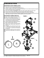
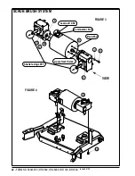
SCRUB BRUSH LIFT ACTUATOR REMOVAL
1
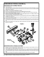
Lower the scrub deck with the scrub brushes installed. Don’t turn the key switch off until disconnecting the battery pack by using
the emergency disconnect
(12)
. This procedure is done to prevent the scrub deck from automatically raising when the key is turned
off.
2
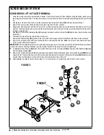
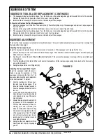
See Figure 6. Remove the nut and screw that secure the Deck Down Limit Cable
(OO)
at the deck mount bracket.
3
Remove the recovery tank (follow the steps in the
Recovery Tank Removal
section).
4
Swing open the drivers seat and from the rear of the machine using two people remove the batteries and battery tray from the
machine. With the batteries and tray removed the brush lift actuator motor top mount is made accessible (located in the lower front
in battery compartment).
5
See Figure 6. Remove the Retaining Ring
(CC)
securing the lower Brush Motor Mount Pin
(DD)
and remove the pin from the scrub
deck mount.
6
Disconnect the brush lift motor wire harness at the motor.
7
Remove the Retainer Ring
(EE)
(closest to the motor) then slide the upper Mount Pin
(FF)
from the chassis mount bracket.
8
Remove the complete motor and drive nut assembly from underneath the machine.
Note:
Do not turn or reposition the drive nut
on the actuator shaft, mark if needed.
IMPORTANT:
After removing the actuator motor and before replacing a new motor or drive nut the IN & OUT limit switches must be set
(or checked) to there correct specifications (see the electrical section for the
Actuator Drive Nut Adjustment
).
10
To disassemble the Drive Nut
(GG)
from the actuator shaft, remove the (2) Screws
(HH)
and separate both Retainers
(II)
&
(JJ)
from the Spring Housing
(KK)
.
11
Remove the (4) Spring Housing Retainer Screws
(LL)
and slide the spring housing and (long) Compression Spring
(MM)
from the
actuator shaft. Then spin the drive nut off the actuator shaft and remove the top (short) Compression Spring
(NN)
.
Note:
See the
Actuator Drive Nut Adjustment
section in this manual to properly install a new drive nut.
12
After adjusting the actuator drive nut follow steps 1-11 in reverse order to re-install the scrub lift motor in the machine.
FIGURE 6
revised 2/05
Summary of Contents for Hydro-Retriever 2800 BR700
Page 2: ......

