FORM NO. 56043055 / HR 2800, HR 2800C / BR 700, BR 700C
- 29
SOLUTION SYSTEM
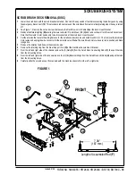
SOLUTION SOLENOID VALVE REMOVAL
Location:
The solenoid valve is mounted on top-middle of the scrub deck.
1
Drain the solution tank using the solution tank drain hose
(4)
.
2
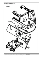
See Figure 1. Remove both the LH & RH Solution Hoses
(A)
&
(B)
at the solution Delivery Tubes
(C)
.
3
Loosen the hose clamp and remove the solution Feed Hose
(D)
from the barb fitting on the Solenoid Valve
(E)
(* see Service Tip
Note).
4
Unplug the solenoid valve wire connection from the machine harness.
5
Loosen the anchor connector at the solution valve mount bracket and separate. Then work the valve/hose assembly from the scrub
deck.
6
Salvage fittings and hose from the old valve and follow steps 1-5 in reverse order to reassemble.
*Service Tip Note:
The solution hoses are often difficult to remove from there barbed fittings. To help remove a hose, back probe
the end of the hose with a screwdriver and apply a small amount of a spray lubricant at the hose fitting and pull firmly to remove.
SOLUTION FILTER AND FLOW CONTROL VALVE ASSEMBLY REMOVAL
1
Drain the solution tank using the solution tank drain hose.
2
See Figure 1. Loosen the (2) Hose Clamps
(F)
and pry off both the solution hoses (inlet & outlet) from the barbed plumbing fittings
attached to the Solution Flow Control Valve
(G)
and Solution Filter Housing
(H)
.
3
Remove the (4) Screws
(I)
that secure the Solution Bracket
(J)
and pull the bracket away from the chassis and then loosen the
solution Cable Clamp
(K)
.
4
Separate the solution cable end from the solution valve handle and complete the removal of the Filter
(H)
and Solution Flow Control
Valve
(G)
from the machine.
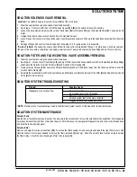
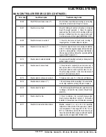
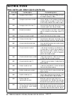
SOLUTION SYSTEM TROUBLESHOOTING
Problem
Possible Cause
Inadequate or no solution flow
No solution in tank
Flow control lever in the off position
Defective solution solenoid valve
Solution system fault in the main controller *
Clogged Solution filter, valves and hoses
* NOTE:
Reference the
Troubleshooting Guide
in the Electrical System section of this manual for further information.
SOLUTION SYSTEM MAINTENANCE
Solution Tank
See the
Know Your Machine
manual section. Weekly empty the solution tank; remove the solution drain hose
(4)
from its storage area
(located underneath the right front of machine chassis). Direct the hose to a designated “Disposal Site” and remove the threaded cap
and flush the tank with clean water.
Solution Filter
Remove and clean the in line solution filter
(20)
. To access the filter housing for removal, work underneath the right front corner of the
machine chassis. No tools are needed to remove the filter (just hand tighten only). Note: The solution tank must be empty to service
the filter strainer. Flush the bowl housing and filter, then reassemble.
revised 2/05
Summary of Contents for Hydro-Retriever 2800 BR700
Page 2: ......

