
38
-
FORM NO. 56043055 / HR 2800, HR 2800C / BR 700, BR 700C
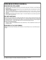
ELECTRICAL SYSTEM
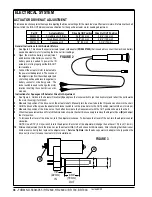
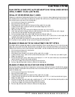
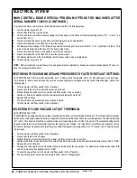
7/8"
(22 mm)
A
2-3/4"
(70 mm)
B
IN
OUT
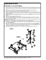
ACTUATOR DRIVE NUT ADJUSTMENT
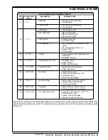
This manual section explains the steps for adjusting the drive nut settings for the machine’s two lift actuator motors. Reference the chart
below to find the IN & OUT dimensional specification for the specific actuator motor needing adjustment.
Part #
Actuator Motor
Drive Nut IN Position Drive Nut OUT Position
56393303
Scrub Brush Lift (Disc)
2-3/8” (60 mm)
5-3/4” (146 mm)
56393303
Scrub Brush Lift (Cyl)
2-3/8” (60 mm)
5-3/4” (146 mm)
56412072
Squeegee Lift
7/8” (22 mm)
2-3/4” (70 mm)
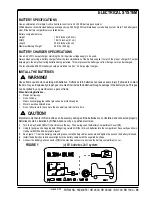
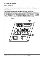
General Instructions for All Actuator Motors
1
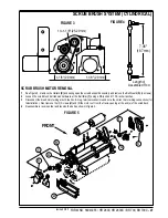
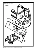
See Figure 2. This shows the special actuator power cord adapter
(PN 56407200)
that is needed to connect the machine’s battery
pack and actuator motor for setting the drive nut limit settings.
2
Open the machine battery compartment
and disconnect the battery connector. The
battery pack is needed to power the lift
actuator motor to properly set the IN & OUT
limit switches.
3
Connect the actuator motor to be tested to
the power cord adapter end. Then connect
the alligator clips from the cord adapter (red
clip to the positive and black to negative) to
battery connector or battery posts. The
rocker switch is used to change the motor
rotation in setting the correct drive nut di-
mension.
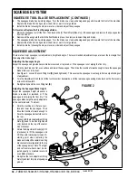
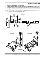
Instructions for Squeegee Lift Actuator Drive Nut Adjustment
4
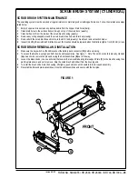
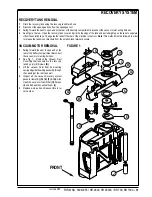
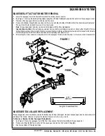
See Figure 3. Hold onto the Actuator Drive Nut
(A)
and press the rocker switch to run the drive motor and retract the nut towards
the motor housing (it’s IN limit).
5
Measure the position of the drive nut on the actuator shaft. Manually turn the steel tube to the IN position as shown in the chart.
6
Hold the drive nut then press the adapter cord rocker switch to run the drive motor to the OUT position (wait until the motor stops).
7
Measure the position of the drive nut on the shaft and compare the measurement with the OUT position shown in the chart.
8
When the measurement doesn’t match the dimension shown in the chart it is necessary to remove the Adjuster Cover
(B)
and adjust
the Out position.
9
To increase the travel of the drive nut, turn the adjuster clockwise. To decrease the travel of the nut, turn the adjuster counter
clockwise.
NOTE: Use a 5/16” (8 mm) wrench to turn the adjuster. Each click of the adjuster will change the nut travel 1/16 inch (1.6 mm).
10
After each adjustment, hold the drive nut, run the actuator IN & OUT and check both dimensions. After checking that the drive nut
limits are set correctly then replace the adjuster cover.
Service Tip Note:
Use the above power cord adapter to help position the
drive nut (in or out) for ease in actuator motor installations.
FIGURE 2
FIGURE 3
revised 2/05
Summary of Contents for Hydro-Retriever 2800 BR700
Page 2: ......


