

FORM NO. 56043055 / HR 2800, HR 2800C / BR 700, BR 700C
- 31
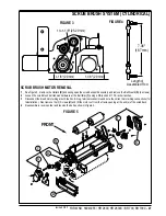
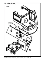
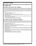
RECOVERY SYSTEM
FRONT
H
I
A
C
E
D
B
F
J
G
B
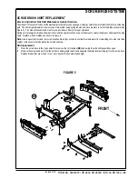
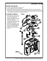
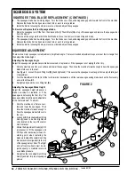
RECOVERY TANK REMOVAL
1
Drain the recovery tank using the recovery tank drain hose.
2
Disconnect the squeegee hose from the squeegee tool.
3
Swing forward the seat to open and at the rear of the battery compartment disconnect the vacuum motor wiring harness.
4
See Figure 1 below. Open the recovery tank cover and grip the top edge of the tank and pull straight up on the tank to separate
it from the solution tank. Then guide the tank off the rear of the machine to the floor.
Note:
This method must be followed in order
to release the tank mount brackets from the solution tank retainer pockets.
FIGURE 1
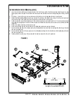
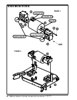
VACUUM MOTOR REMOVAL
1
Swing forward the seat to open and at the
rear of the battery compartment disconnect
the vacuum motor wiring harness.
2
See Fig. 1. Remove the Vacuum Duct
Cover
(A)
that is secured to the recovery
tank by a qty (6) Screws
(B)
.
3
Lift the vacuum motor from its mounting
cavity and guide the wiring assembly through
the opening at the rear tank wall.
4
Inspect all the vacuum/recovery system
gaskets, items
(C)
,
(D)
,
(E)
,
(F)
, &
(G)
. Also
clean the vac motor foam Filter
(H)
,
Screen
(I)
, and Exhaust Acoustical Foam
(J)
.
5
Replace worn parts and reassemble in re-
verse order.
revised 2/05
Summary of Contents for Hydro-Retriever 2800 BR700
Page 2: ......


