40
-
FORM NO. 56043055 / HR 2800, HR 2800C / BR 700, BR 700C
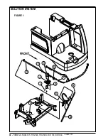
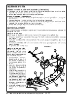
ELECTRICAL SYSTEM
CURTIS CONTROLLER
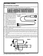
The HR 2800 / BR 700 wheel drive system uses a .8 horsepower, 24V, DC permanent magnet motor. The system uses a Curtis Model
1235 solid-state controller to regulate the speed and direction of the drive wheel. The controller unit is located to the left of the operator
seat, behind the louvered electrical access panel. The signal input to the controller is regulated by a potentiometer attached to the
foot activated drive pedal.
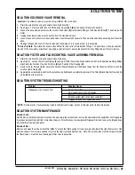
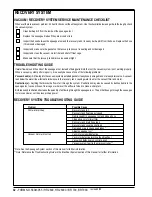
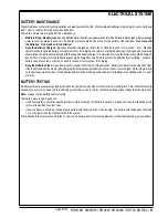
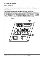
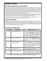
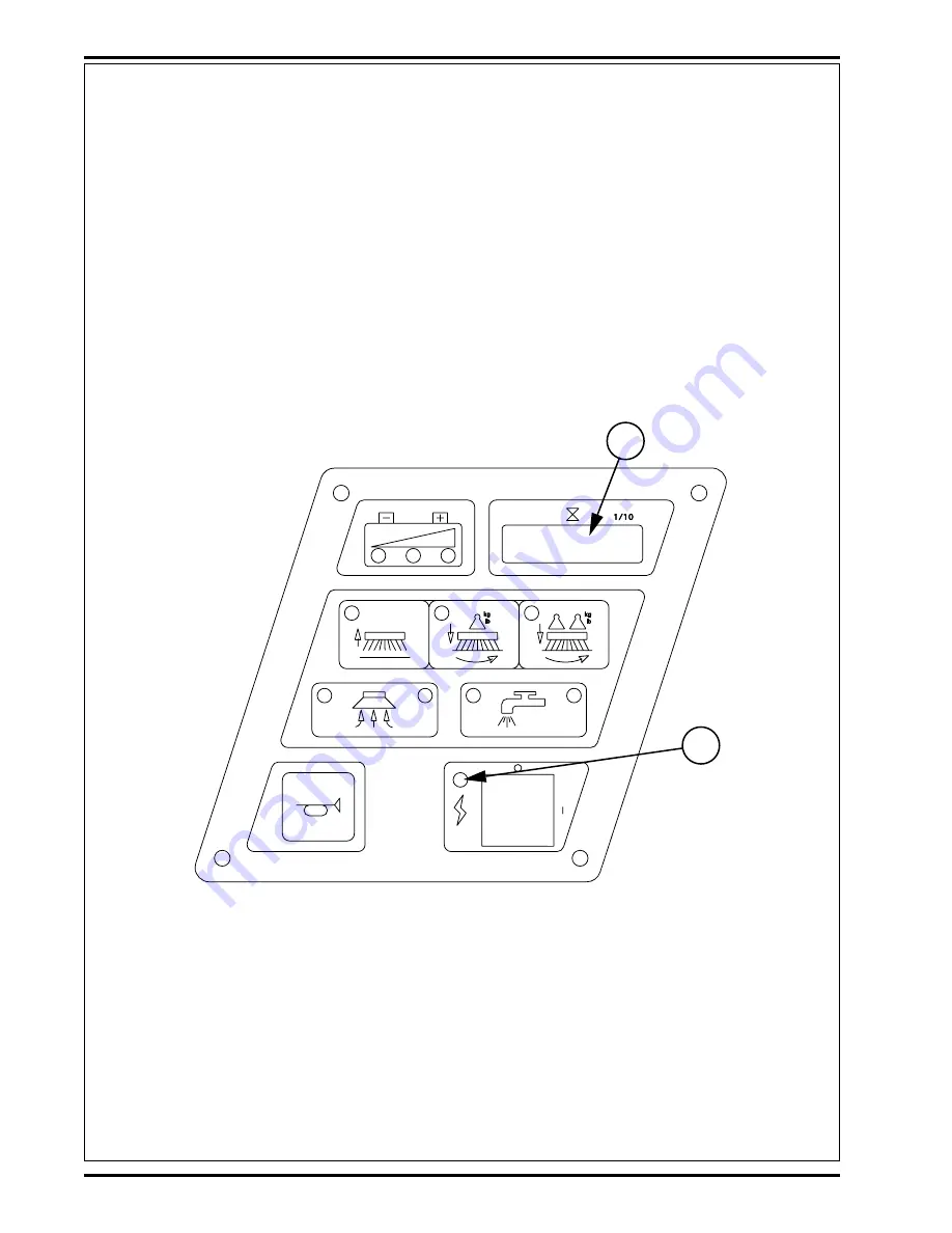
FUNCTION OF THE SPEED CONTROLLER STATUS LIGHT AND DISPLAY
The Curtis 1235 speed control will output a fault code if there is a problem associated with the speed control and wheel drive system.
See Figure 1. If a speed control fault occurs, the Hourmeter/Status display
(E)
will indicate “Err 03”. When the Err03 is being displayed
and detects a fault the Red Indicator
(F)
located by the key switch will flash a special error code sequence until the fault is corrected.
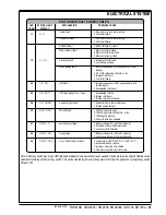
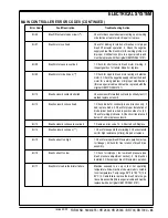
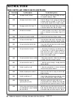
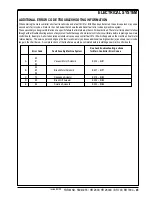
See table 1 for a description of the fault indications and descriptions.
Service Note:
Instructions on how to read the error code status
light. Example, OO O = two light flashes, a short pause. One flash, long pause and the code will be repeated.
F
E
FIGURE 5
revised 2/05
Summary of Contents for Hydro-Retriever 2800 BR700
Page 2: ......


