

FORM NO. 56043055 / HR 2800, HR 2800C / BR 700, BR 700C
- 15
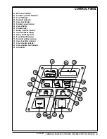
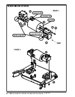
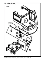
WHEEL DRIVE SYSTEM
C
D
FRONT
G
F
H
E
I
J
K
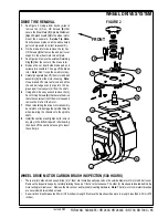
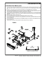
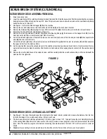
DRIVE TIRE REMOVAL
1
See Figure 2. Using a 6mm hex key wrench
remove the (4) Soc. HD Screws
(E)
that
secure the Steer Plate
(F)
, Spindle Weldment
(G)
and Splash Guard
(H)
to the wheel motor
mount then separate.
Service Tip Note:
Punch witness marks on all the above listed
parts to help assist in correct re-assembly.
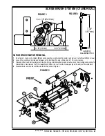
2
On the brake rotor side remove the (4) Soc.
HD Screws
(I)
that fasten the end bell cover
support to the wheel motor mount plate.
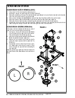
3
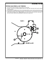
See Figure 3. Remove the external Retaining
Ring
(S)
from the center of the brake rotor.
4
Remove the out board side brake pad and
caliper arm assemble. Then pry off the brake
rotor.
Note:
Don’t loose the small rotor key.
5
Carefully separate (tap off) the motor end bell
assembly
(J)
from the motor housing.
Note:
Use a brass drift or piece of wood and strike
the end bell edge evenly at points 120 de-
grees apart to slowly work it from the shaft.
6
Using a 5mm hex key wrench remove the (4)
Soc. HD Cap Screws
(K)
that secure the drive
tire to the center section of the motor case and
remove the tire from the motor.
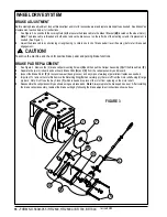
7
When reinstalling the drive motor assembly
be careful not to damage the spindle threads
when lowering the chassis onto the spindle
shaft.
8
Install the castle nut and tighten nut to remove
any play in the bottom tapered roller bearing
then back off the castle nut enough to insert
the cotter pin.
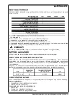
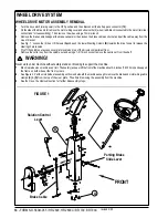
WHEEL DRIVE MOTOR CARBON BRUSH INSPECTION (500 HOURS)
•
There are (6) carbon brush assemblies, (4) of them are located equally spaced on the outside diameter of motor end bell cover.
Remove the inspection caps by carefully twisting the cap a 1/8 of a turn clockwise. The other (2) brushes are located behind the
motor wiring terminal cover. Remove the black cover and terminal mounting hardware.
Note:
The (4) motor commutator brushes
are secured with two slotted screws.
•
A new carbon brush measures 20mm (.780 inches) in length. Replace the brushes when worn to a length less than 9.5mm (.375
inches).
FIGURE 2
revised 2/05
Summary of Contents for Hydro-Retriever 2800 BR700
Page 2: ......


