

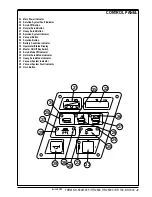


12
-
FORM NO. 56043055 / HR 2800, HR 2800C / BR 700, BR 700C
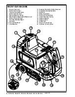
KNOW YOUR MACHINE
DESCRIPTION OF INDICATORS ON THE CONTROL PANEL (CONTINUED)
Vacuum System Indicator (37):
•
This indicator will be YELLOW if the vacuum/squeegee system is in the AUTO mode and the throttle is in the neutral position. This indicates that
the vacuum system is enabled but the vacuum is currently off.
•
This indicator will be GREEN if the vacuum is currently on. This indicates that the system is in the AUTO mode and the throttle is not in neutral
or that the vacuum system is in the ON mode.
•
This indicator will FLASH GREEN if the shutoff delay is keeping the vacuum on. This occurs if the vacuum system is in the AUTO mode and the
throttle goes to the neutral position. This will also occur if the vacuum system is turned off while it was in either the AUTO or ON modes. The
shutoff delay will turn the vacuum off after the delay period.
•
This indicator will be OFF if the vacuum/squeegee system if in the OFF mode.
Vacuum System Fault Indicator (38):
•
This indicator will flash red if there is a fault in the vacuum or squeegee systems. This will be accompanied by an error indication on the Hour
Meter / Status Display
(32).
•
This indicator will be RED and the Hour Meter / Status Display
(32)
will show “FULL” if the recovery tank float valve has closed. If this indication
occurs and the tank is not full, see the
Troubleshooting
section.
Solution System Indicator (28):
•
This indicator will be YELLOW if the solution system is in the AUTO mode and the throttle is in the neutral or reverse positions. This indicates
that the solution system is enabled but the solution flow is currently off.
•
This indicator will be GREEN if the solution system is in the AUTO mode and the throttle is in the forward position. It will also be GREEN if the
solution system is in the MOMENTARY ON mode. This indicates that the solution flow is currently on.
•
This indicator will be OFF if the solution system is in the OFF mode.
Solution System Fault Indicator (24):
•
This indicator will flash red if there is a fault in the solution system. This will be accompanied by an error indication on the Hour Meter / Status
Display
(32).
Main Power Indicator (23):
•
This indicator will be GREEN when the key switch is ON.
•
This indicator will flash RED if there is a system fault that requires turning the Master ON/OFF Key Switch
(33)
off to reset.
•
This indicator will flash fault codes from the Curtis Speed Control if a fault exists. This will be accompanied by an “Err03” indication on the
Hourmeter/Status Display
(32)
.
DESCRIPTION OF THE BATTERY CONDITION INDICATORS
The battery condition indicators will give an indication of the state of charge of the batteries. The battery condition monitor will retain the state-of-charge
even if the key has been turned off. The state-of-charge indication is reset to full charge when the batteries have been recharged. It is also possible
to choose between two different low voltage thresholds depending on whether maintenance free or standard batteries are being used
(have qualified
service engineer perform this selection*)
. NOTE: The following percentages are based on
useable
battery capacity not total battery capacity.
Therefore, 100% discharge = 80% of total battery capacity for standard wet cell batteries or 70% of total battery capacity for maintenance free batteries.
Green Indicator
= full charge down to 50% discharge
Green & Yellow Indicator
= 50% discharge down to 75% discharge
Yellow Indicator
= 75% discharge down to 90% discharge
Yellow & Red Indicator
= 90% discharge down to 95% discharge
Red Indicator
= 95% discharge down to 99% discharge
Flashing Red Indicator
= 100% discharge - scrub system will automatically shut down
*Important Note:
See the
Main Control Board Special Program Options
manual section (located in the electrical system) and follow the instructions
for setting the low voltage cutout threshold.
DESCRIPTION OF HOURMETER / STATUS DISPLAY
The 5 character display in the upper right corner of the control panel is primarily used as a display for the hourmeter function. This display is also used
to display the following information depending upon which mode the control is in:
•
Error codes*
•
Brush pressure adjustment setting for normal scrub mode*
•
Display of control system default parameters*
•
Recovery tank FULL indicator*
* NOTE: Reference (in the Electrical System manual section) the Main Control Board Troubleshooting Guide and the Control Board Special Program
Options sections. These sections will explain the machine error code descriptions and scrub system controller default parameter changes.
Emergency Stop Switch / Battery Disconnect (12)
: This will remove all power from the machine.
revised 2/05
Summary of Contents for Hydro-Retriever 2800 BR700
Page 2: ......


