


62 - FORM NO. 56043097 / Adgressor
™
/ BR 850S, 850CS, 950S, 950CS, 1050S, 1050CS
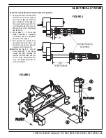
ELECTRICAL SYSTEM
Scrub ON/Pressure Decrease Switch (D):
This switch is used to control the output to the scrub deck lift actuator. Pressing and releasing this switch will cycle the actuator output through 4
states. These are:
1 - output off, direction = up
2 - output on, direction = down
3 - output off, direction = down
4 - output on, direction = up
When the output is in state 1, the actuator output is turned off. The scrub pressure decrease indicator should be off. If the indicator is fl ashing green,
this indicates that the control is sensing current fl ow through the actuator (shorted output driver, control error). If the scrub pressure decrease switch
was the last switch pressed, it is possible to momentarily activate the actuator output using the horn switch. This can be used to jog the actuator to
allow precise positioning of the actuator. NOTE: the actuator can only move in this situation if it is not at its up limit.
When the output is in state 2, the actuator output is turned on. The scrub pressure decrease indicator should be green or fl ashing green. The
indicator will be a steady green if the control senses current fl ow through the actuator. It will fl ash green if no actuator current fl ow is sensed (actuator
at limit, open circuit, open output driver). The horn switch has no effect in this state.
When the output is in state 3, the actuator output is turned off. The scrub pressure decrease indicator should be off. If the indicator is fl ashing green,
this indicates that the control is sensing current fl ow through the actuator (shorted output driver, control error). If the scrub pressure decrease switch
was the last switch pressed, it is possible to momentarily activate the actuator output using the horn switch. This can be used to jog the actuator to
allow precise positioning of the actuator. NOTE: the actuator can only move in this situation if it is not at its down limit.
When the output is in state 4, the actuator output is turned on. The scrub pressure decrease indicator should be green or fl ashing green. The
indicator will be a steady green if the control senses current fl ow through the actuator. It will fl ash green if no actuator current fl ow is sensed (actuator
at limit, open circuit, open output driver). The horn switch has no effect in this state.
Scrub ON/Pressure Increase Switch (F):
This switch is used to control the output to the squeegee lift actuator. Pressing and releasing this switch will cycle the actuator output through 4
states. These are:
1 - output off, direction = up
2 - output on, direction = down
3 - output off, direction = down
4 - output on, direction = up
When the output is in state 1, the actuator output is turned off. The scrub pressure increase indicator should be off. If the indicator is fl ashing green,
this indicates that the control is sensing current fl ow through the actuator (shorted output driver, control error). If the scrub pressure increase switch
was the last switch pressed, it is possible to momentarily activate the actuator output using the horn switch. This can be used to jog the actuator to
allow precise positioning of the actuator. NOTE: the actuator can only move in this situation if it is not at its up limit.
When the output is in state 2, the actuator output is turned on. The scrub pressure increase indicator should be green or fl ashing green. The
indicator will be a steady green if the control senses current fl ow through the actuator. It will fl ash green if no actuator current fl ow is sensed (actuator
at limit, open circuit, open output driver). The horn switch has no effect in this state.
When the output is in state 3, the actuator output is turned off. The scrub pressure increase indicator should be off. If the indicator is fl ashing green,
this indicates that the control is sensing current fl ow through the actuator (shorted output driver, control error). If the scrub pressure increase switch
was the last switch pressed, it is possible to momentarily activate the actuator output using the horn switch. This can be used to jog the actuator to
allow precise positioning of the actuator. NOTE: the actuator can only move in this situation if it is not at its down limit.
When the output is in state 4, the actuator output is turned on. The scrub pressure increase indicator should be green or fl ashing green. The
indicator will be a steady green if the control senses current fl ow through the actuator. It will fl ash green if no actuator current fl ow is sensed (actuator
at limit, open circuit, open output driver). The horn switch has no effect in this state.
Vacuum Switch (O):
This switch is used to toggle the state of the vacuum motor. Pressing and releasing this switch will alternately turn the vacuum motor on and off.
The indicator (P) provides the following status information:
Off - Vacuum motor output is off and there is no vacuum motor current sensed.
Steady Green - Vacuum output is on and there is normal vacuum motor current sensed.
Brief On Green Flash - Vacuum motor output is off and vacuum motor current is being sensed (abnormal condition).
Brief Off Green Flash - Vacuum motor output is on and vacuum motor current is not being sensed (abnormal condition).
Flashing Red – Vacuum motor overload has occurred.
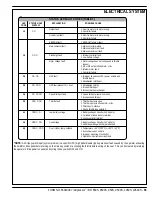
SERVICE TEST MODE (CONTINUED)
Summary of Contents for Adgressor BR 1050CS
Page 81: ......
Page 82: ...www nilfisk advance com 2006 ...


