


FORM NO. 56043097 / Adgressor
™
/ BR 850S, 850CS, 950S, 950CS, 1050S, 1050CS - 27
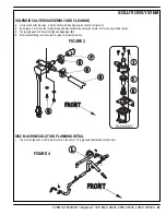
WHEEL DRIVE SYSTEM
Right Side View
Front View
A
B
POTENTIOMETER INSTALLATION AND ADJUSTMENT
WARNING!
The adjustment of the potentiometer is to set the drive pedal for a neutral drive motor operation. If the pot is not adjusted properly, the machine will
creep in either FWD or REV.
1 See Figure 8. Install the pot into the Mount Housing (AK) and tighten the attachment nut.
2 Connect loosely together both the Link Rod (AE) to the Pedal (AF), and the Throttle Lever (AJ) to the potentiometer input shaft. Then tighten
only the Link Rod (AE) pedal mounting Hardware (AG). Note: Check the movement of the Foot Pedal (AF) it must move freely in both Fwd and
Rev.
3 See Figure 8 inset. Attach test leads from a volt/ohm meter (set meter on 0x100 scale) to the YEL and VIO wire connection points on the
potentiometer to check it’s total resistance (example 4800 Ohms).
4 Next connect the ohmmeter test leads to the GRA and VIO potentiometer connection points. Then using a small screwdriver, turn the shaft end
on the pot to half the total resistance previously measured. Example: 4800 Ohms divided by 2 = 2400 Ohms. Then without turning the shaft,
tighten the Screw (AI) and Nut (AH) to secure the setting at the Throttle Lever (AJ).
5 Follow steps 1-2 in reverse order (see Potentiometer Removal steps) to fi nish the installation. Then test-drive the machine for proper speed
and FWD/REV directional control.
DRIVE PEDAL NEUTRAL ADJUSTMENT & PEDAL REPLACEMENT
If the drive pedal has been removed or replaced, the neutral position for the pedal will have to be set. Follow the steps below to accomplish this.
WARNING!
Disconnect the machine’s battery pack connector (13) before servicing.
•
Note: See Figures 8 & 9. Before making any adjustments, inspect the Torsion Spring (AL) for defects and the correct positions of both spring
ends (repair or replace).
To Adjust Pedal Spring
1 Loosen
the
Screw
(AM) & Nut (AN), the screw with bushing is positioned between both Fwd & Rev torsion spring ends. Its placement controls
the needed pre-load pressure to eliminate excessive pedal free-play and a balanced spring rate to return the pedal to a centered (neutral)
position.
2 Push the screw back into the pedal frame slot to increase spring tension and eliminate pedal free play. Then tighten the screw & nut being
careful not to pull on the linkage connection to the pot shaft and disturb (move) its neutral setting.
To Replace Pedal or Spring
3 Position the torsion spring ends (A & B) as shown. This is with the bushing and screw not installed.
4 Place the bushing inside the pedal channel pilot it into position using a scratch awl or a pin punch.
5 Then pivot (press) the pedal and insert the screw from the opposite side pushing the guide tool out.
6 Use a screwdriver to tap and pry the bushing back in the pedal slot to increase spring tension.
7 Work the bushing back & forth on both sides of the pedal to obtain equal spacing. Then tighten the screw and nut.
8 A correctly adjusted drive pedal will have minimal amount of free-play when selecting a drive direction.
9 Reconnect the batteries and test the machine to make sure it does not “creep” forward or reverse when the pedal returns to neutral.
10 Service Tip: Also confi rm the Hourmeter/Status Display (G) is free of the error code 03 (drive system fault). If error 03 is shown the throttle is
not set properly for the potentiometer and or drive pedal neutral position. Check both again and readjust.
FIGURE 9
Summary of Contents for Adgressor BR 1050CS
Page 81: ......
Page 82: ...www nilfisk advance com 2006 ...


