


38 - FORM NO. 56043097 / Adgressor
™
/ BR 850S, 850CS, 950S, 950CS, 1050S, 1050CS
SOLUTION SYSTEM
FIGURE 1
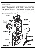
FUNCTIONAL OVERVIEW
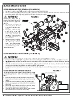
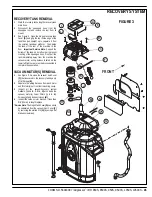
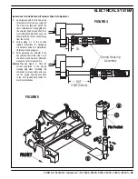
See Figure 1. The plastic (polyethylene) molded main body structure fulfi lls three (design) functional uses. They are the platform for the operator’s
seat, mount cavity for the electrical panel and as the storage tank for the machine’s scrubbing solution. The solution tank fi ll capacity is 42 gallons
(157L). Plumbed into the fl ow control valve hose outlet is a serviceable solution fi lter to keep debris from entering the solenoid valve. Also fi tted to
the fl ow control valve is a short fl exible drain hose to empty the tank for system maintenance.
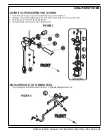
The solution system uses (2) valves to stop, start and regulate the amount of solution dispensed onto the fl oor. Located underneath the right side of
the solution tank two feet back from the front is mounted the electrical solution solenoid valve L1. Its function is to stop and start the solution fl ow to
the scrub brushes. Located on the operator’s steering column support is the solution lever (tee handle). The lever and connected cable move the
fl ow control valve arm that regulates solution fl ow to meet a specifi c operator’s scrub application.
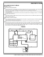
See Figure 2. The electrical circuit that turns on (energizes) the solenoid coil L1 is activated through the E1 control panels switch buttons (touch
pad). Note: See the Know Your Machine section in this manual for a detailed explanation of the complete solution operation modes.
During normal machine scrubbing the solution system’s Auto Mode is selected and works in conjunction with the (A1) wheel drive speed controller
and the foot pedal (throttle). This input activates the scrub system’s outputs to turn on & off the (L1) solenoid valve. The solution fl ows to the scrub
brushes any time the manual fl ow control valve is open, the scrub deck is lowered and the drive pedal is pushed into the forward position. Note:
When the solution on/off button is turned off, no fl ow can occur regardless of the manual fl ow control being on, drive pedal activated and the scrub
deck down.
FRONT
Electrical Solenoid
Valve (L1)
Flow Control Valve (C)
Solution Lever
Solution Tank
B
A
Smart Solutions
Valve
Summary of Contents for Adgressor BR 1050CS
Page 81: ......
Page 82: ...www nilfisk advance com 2006 ...