


FORM NO. 56043097 / Adgressor
™
/ BR 850S, 850CS, 950S, 950CS, 1050S, 1050CS - 43
RECOVERY SYSTEM
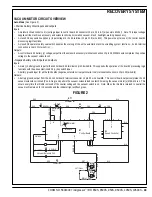
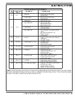
VACUUM MOTOR CIRCUIT OVERVIEW
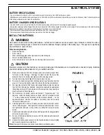
Auto Mode (See Figure 2)
+ Positive battery circuit inputs and outputs
Inputs:
•
A Solenoid circuit control coil (+) voltage input to control board E1 connector J2 pin #’s 6 & 7 (wire colors Brn/Yel). Note: This input voltage
supplies all the machine’s accessory and solenoid coil circuits (solution, vacuum, brush, headlight, warning beacon etc.).
•
A closed S1 key switch supplies (+) input voltage to the E1 terminal J2 pin #10 (wire Brn). This powers up (turns on) the control board’s
processing logic functions.
•
A closed S2 operator safety seat switch enables the starting of the entire automatic machine scrubbing system functions. Its E1 terminal
connection is J4 pin #11 (wire Orn).
Outputs:
•
A control board E1 battery (+) voltage output from the solenoid accessory terminal connection J2 pin #8 Wht/Brn wire completes the positive
voltage to the vacuum solenoid coil.
- Negative battery circuit inputs and outputs
Inputs:
•
A main (-) battery ground input for the control board E1 terminal J4 pin #8 wire Blk. This supports the operation of the board’s processing logic
functions with the above mentioned S1 (+) key switch input.
•
A battery ground input for all the (E1 boards) negative solenoid coil output circuits. Its E1 terminal connection is J2 pin #5 (wire Blk).
Outputs:
•
A battery ground output from the E1 control board terminal connector J2 pin #2 wire Gra/Blk. This control board output completes the K2
vacuum solenoid coil circuit (Pos. & Neg.) and pulls in the vacuum solenoid load contact K2 making the vacuum motor(s) M5 & M6 run. This
occurs every time the throttle is moved off its neutral setting and the vacuum switch is on. Note: When the throttle is returned to neutral the
vacuum will remain on for 10 seconds and the indicator light will fl ash green.
FIGURE 2
M5
Motor, Vac
M
K2
Vacuum Solenoid Coil
S2
Sw, Seat
2
1
BT1
Battery, 36 Vdc
M6
Motor, Vac
M
S1
Sw, Spst
Key
F3
F4
K2
Contact N.o.
RED
BLK
RED
BRN/YEL
BRN/YEL
BRN
WHT/BRN
WHT/BRN
GRA/BLK
BLK
WHT
WHT
RED
BRN/RED
BLK
BLK
BRN/RED
BRN
ORN
ORN
ORN
B+ 1
B+ 2
KEY
SW
.
SEA
T
SW
.
B-
ACC
VACUUM
A1
Speed Controller
Interface
Thermistor
I -- V
AC
E1
Control Board
OPTIONAL
PIN15 -- KSI
J2-7
J2-6
J2-10
J4-1
1
J2-8
BLK
J4-8
J2-5
B-1
B-2
J2-2
+
-
+ -
J4-6
Summary of Contents for Adgressor BR 1050CS
Page 81: ......
Page 82: ...www nilfisk advance com 2006 ...


