IV
Part Descriptions
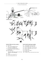
1 TIRF2 attachment
35
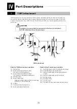
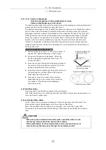
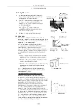
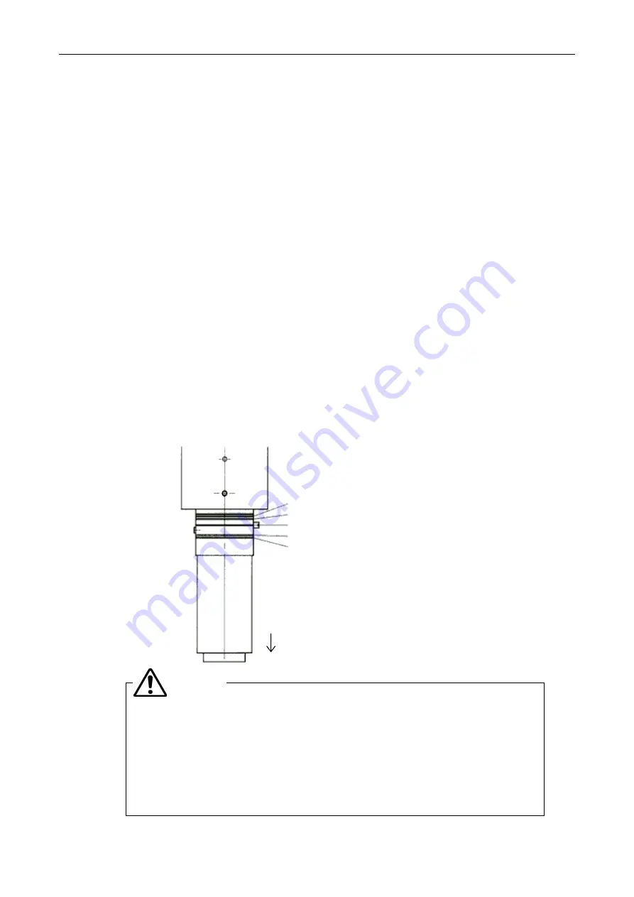
(6) Indices
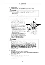
(7) Condenser lens locking screw
(8) Focal point adjustment knob
You can change the focal point of the laser beam along the path of the objective's optical
axis by moving this knob back and forth.
When the laser beam is focused on the objective's pupil surface, the objective-emitted
laser beam should form parallel rays. If the focal point is not focused on the pupil surface,
the laser beam cannot be parallel rays. So, even when the optical path of the laser beam is
tilted at a critical angle or greater relative to the specimen, the image quality will be
degraded or the specimen will be damaged.
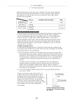
Whenever replacing the objective, follow the steps specified below to adjust the focal point
of the laser beam.
1) Turn the laser position adjustment knob to move the laser beam just above the
objective.
2) Loosen the condenser lens locking screw with a hexagonal screwdriver.
3) Move the focal point adjustment knob back and forth while observing the laser beam
on the ceiling of the room or chamber. Try to minimize the spot illuminated by the
laser; or at least try to reduce the width of the illuminated spot smaller than the
double of the minimum size.
4) When adjustment is complete, tighten the condenser lens locking screw with a
hexagonal screwdriver.
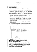
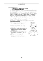
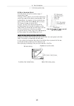
Indices (circumferential grooves) are provided to indicate various positions of the focal
point adjustment knob that correspond to the objectives used for TIRF observation. Use
these indices to guide laser focal point adjustment.
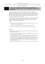
Never attempt to look into the laser beam. (FDA CDRH: Class II,
EN60825-1: Class 2, IEC60825-1: Class 2)
The objective emits a powerful laser beam. When adjusting the focal point
adjustment knob or condenser lens locking screw, never attempt to look
into the objective or the areas near the objective from above or below the
stage as the lens emits a powerful laser beam toward the top and bottom
sides of the stage. To protect your eyes and skin from exposure to laser
beam reflections, never place or mount any reflective materials on the
stage, in the room, or on the chamber ceiling.
WARNING
100
×
/1.4VC
-
Plan Apo VC100
×
H
60
×
/1.4VC
-
Plan Apo VC60
×
H
60
×
/1.45
-
Plan Apo TIRF60
×
H
100
×
/1.45&1.4
-
Plan Apo TIRF100
×
H&100
×
H
60
×
/1.4
-
Plan Apo 60
×
H
Indices
Front
(objective side)
Summary of Contents for TIRF2
Page 1: ...TIRF2 SYSTEM FOR TE2000 INSTRUCTIONS M339E 04 12 NF 2 ...
Page 2: ......

